
User's Manual

SASL User Guide v1.40 - Part # ITCS-A-100-001 v1.40 May 2014
6
ELECTRICAL INSTALLATION
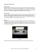
POE Power Input
POE power input is available only for the ITCS-A-210 and ITCS-A-212 using the RJ-45 connector
as shown in Figure 4. Connect POE power supply and plug it in to a suitable mains outlet and the
POE Bias T. POE power, DC Input equivalent to IEEE 802.3at. Note that the power for the POE
bias T should be located in close proximity to the SASL and should be accessible to enable easy
disconnection of the power to the SASL in case of emergency or when servicing.
AC Mains Input
AC mains input is an IEC connector as shown in Figure 4. Connect the provided IEC mains cord to
the power supply and plug it in to a suitable mains outlet. Note that the mains outlet must be
located in close proximity to the SASL and must be accessible to enable easy disconnection of the
mains supply to the SASL in case of emergency or when servicing. The form and location of the
AC mains input is the same on the ITCS-A-210 and ITCS-A-212.
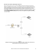
Ethernet
The Ethernet LAN connection uses the industry standard RJ-45 connector. A suitable Ethernet
cable fitted with an RJ-45 plug is connected to the SASL Array Controller box as shown in Figure 4.
The SASL is factory programmed with a fixed IP address which is shown on the label adjacent to
the Ethernet connector. The form and location of the Ethernet connection Input is the same on the
ITCS-A-210 and ITCS-A-212.
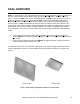
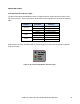
Figure 4
ITCS-A-210 and ITCS-A-212 Power and Ethernet Connections are similar in form and location.