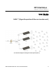
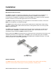
User Guide (provisional) SASL™ (Signal Acquisition & Source Location unit) RF Controls Intelligent Tracking and Control System (ITCS™) SASL Installation Guide V0.9 - Part # ITCS-A-100-001v0.
Introduction This SASL™ User Guide provides the basic information needed to install and set up an individual SASL antenna unit. This guide is not intended to provide instructions for installing, configuring and calibrating the RF Controls Intelligent Tracking and Control System (ITCS™). Detailed instructions are provided in the System Integrator Installation Manual and Programmer’s Reference Guide.
SASL OVERVIEW SASL is a multi-protocol, multi-regional Radio Frequency Signal Acquisition & Source Location unit, which is used to Identify and locate RFID tags operating in the UHF 860 – 960 MHz frequency band. A number of SASL units may be used together with an ITCS ‘Edge Server’ to form an Intelligent Tracking and Control System (ITCS).
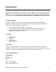
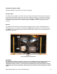
INDICATOR LIGHTS There are four lights on the back of the SASL located on the Sirit RFID reader. The indicator lights on the Sirit RFID reader are: • • • • Sense – Indicates that the reader has detected a tag in the RF field Transmit – indicates that the reader/writer transmitter is operating (RF on) Fault – Indicates that there is a fault Power – Indicates that power is applied to the reader Note that when the Sirit reader is performing power on auto-test, the indicator lights will flash momentarily.
Installation MECHANICAL INSTALLATION The SASL is provided in its standard configuration with a mounting bracket for installation in a landscape orientation. An optional portrait mounting bracket is available if under special circumstances an installation configuration requires the SASL to be installed in portrait orientation. Contact a member of our technical support team for more information.
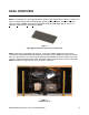
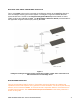
ELECTRICAL INSTALLATION Electrical installation requires the connection of two plugs. AC Mains Input AC mains input is provided on an IEC connector on the power supply module as shown in figure 5. Connect the provided IEC mains cord to the power supply and plug it in to a suitable mains outlet. Note that the mains outlet must be located in close proximity to the SASL and must be accessible to enable easy disconnection of the mains supply to the SASL in case of emergency or when servicing.
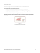
MULTIPLE SASL UNITS CONFIGURED AS AN ITCS Two or more SASL units may be connected via an Ethernet network to an ITCS Edge Server to form an Intelligent Tracking and Control System. The diagram in figure 6 illustrates the basic system architecture. The RF Controls System Integration Manual provides details on how to install, configure and calibrate an ITCS. The Programmers Reference Guide provides details of the Application Program Interface (API) used by the ITCS.
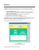
Software The SASL is provided with a basic test program on a CD, to run on a Microsoft™ Windows® equipped Personal Computer. The program enables you to carry out a number of basic tests: • • • • • Command the SASL to transmit Adjust the RF output power of the SASL as a percentage of maximum power. (Note: the maximum output power is factory set to the maximum RF output power allowed for the particular country of destination).
USING THE TEST PROGRAM Set RF Output Power Enter the desired RF output power as a percentage of the maximum power into the Set Power box. Click the set Power button. (Note: the actual maximum Radiated RF Power is factory set to comply with the radio regulations in the country of use. In the USA and Canada this is 4 Watts EiRP). Set Beam The beam direction may be pointed to any desired direction within ± 30 degrees of a line perpendicular to the centre of the SASL antenna panel.
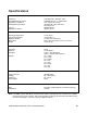
Specifications General Frequency RF Radiated Output Power Regulatory Compliance Reading/writing Protocols FCC ID Application Interface UHF band: 860 – 960 MHz *Note Adjustable from 0.1 to 4 Watts EiRP FCC, CFR47 Part 15.247 ISO18000-6C / EPC UHF Gen 2 EM 4122 (TTO) WFQITCSA100 ISO/IEC 24730 Environmental Operating Temperature Storage Temperature Relative Humidity Dimensions Weight 0 to 60 deg C -40 to 85 deg C 5 to 95% non-condensing 64in x 32in x 6in (162.5 x 81.25 x 15.
Safety Instructions This unit emits Radio Frequency non-ionizing radiation. The installer must ensure that the antenna is located or pointed such that it does not create an RF field in excess of that permitted by the Health and Safety Regulations applicable to the country of installation.