
User Guide
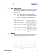
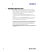
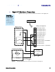
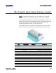
Table Of Contents

Appendix A
IN610 DIO Interface Module
INfinity 610 User’s Guide
81
A IN610 Digital Input/Output Interface Module
NOTE: The DIO Interface Module may not be available for some models.
Please contact your Federal Signal/Sirit Representative for availability.
The Sirit DIO Interface Module provides an easily accessible interface to the
reader’s four digital inputs and four digital outputs. Screw terminals provide
secure signal connections and eight LEDs indicate I/O activation. The
interface also provides +12 Vdc, +15 Vdc, and ground.
The module connects to the reader’s existing digital I/O connector and 15
Vdc power connector. Reader power passes through the interface module.
Term Signal Name D-Sub Pin Description
1, 3, 5, 9, 13,
15, 17, 19
GND 7,12,13,14,15 Ground
2 Terminal4 6 Digital Input 4 – optically isolated
4 Terminal3 5 Digital Input 3 – optically isolated
6 Terminal2 3 Digital Input 2 – optically isolated
7 GND 7,12,13,14,15 Ground
8 Terminal1 2 Digital Input 1 - optically isolated
10 Output4 11 Digital Output 4 - open collector
11 GND 7,12,13,14,15 Ground
12 Output3 10 Digital Output 1 - open collector
14 Output2 9 Digital Output 0 - open collector
16 Output1 8 Digital Output 1 – open collector
18 +15 Volts — +15Vdc
20 +12 Volts — +12 Vdc (from onboard regulator)