
User's Manual
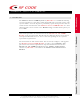

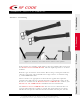


Table Of Contents
- User Manual
- Contents
- 1 – Introduction
- 2 – Hardware
- Front View – LED Indicators
- Rear View – Data Connections
- Antennas – Positioning
- Environmental Limits
- Tag Positioning
- 3 – Firmware
- File System
- Upgradeable Firmware
- Reader Setup
- Configuration Files & Default Settings
- 4 – Troubleshooting
- A – List of Acronyms
- B – Index
- C – FCC Compliance

© Copyright 2003 RF Code, Inc. All rights reserved. UM-C2020-R02-20030422.
No copying of this material is allowed without prior written permission. Page 7 of 27.
USER MANUAL – Mantis™ II 433.92MHz Reader
7
Antennas – Positioning
Figure 2.3 – Standard ¼-wave helical antennae shown in various positions.
Each antenna post supplies an RF signal to the two parallel radio receivers in
the Mantis™ II 433.92MHz Reader. Antenna input impedance is 50 ohms
nominal.
Both the type of antennas used and the Reader range setting determine the
effective read range. The normal Reader-range features are defined using
¼-wave helical antennas.
These antennas are appropriate for most Reader applications. Optional
antennas that offer diverse receiving properties or extend the range of the
Reader are available for the Mantis™ II 433.92MHz Reader. Contact your
Mantis™ II 433.92MHz Reader distributor for more information.
The Mantis™ II 433.92MHz Reader has two receiver channels that can
operate independently or jointly to provide Tag signal diversity reception.
The Reader can operate with one antenna on either antenna post, but the