
Specifications


4
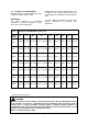
Table 1
Clearance to Combustibles, inches (cm)
Burner
Rating
A B B1 C1 C2 C3 D1 D2 E
60
74 (188) 29 (74) 41 (105) 20 (51) / 10* (26)* 8 (21) 22 (56) 8 (21) 12 (31) 12 (31)
80
74 (188) 29 (74) 41 (105) 20 (51) / 10* (26)* 8 (21) 22 (56) 8 (21) 12 (31) 12 (31)
100
74 (188) 32 (82) 41 (105) 20 (51) / 10* (26)* 8 (21) 22 (56) 8 (21) 16 (41) 12 (31)
125
74 (188) 39 (99) 47 (120) 20 (51) / 10* (26)* 8 (21) 22 (56) 20 (51) 18 (46) 12 (31)
150
74 (188) 39 (99) 48 (122) 20 (51) / 10* (26)* 8 (21) 22 (56) 20 (51) 18 (46) 12 (31)
170
86 (219) 48 (122) 48 (122) 20 (51) / 10* (26)* 11 (28) 22 (56) 20 (51) 20 (51) 12 (31)
200
86 (219) 48 (122) 48 (122) 20 (51) / 10* (26)* 11 (28) 22 (56) 20 (51) 20 (51) 12 (31)
Building material with a low heat tolerance (such
as plastics, vinyl siding, canvas, tri-ply, etc.)
may be subject to degradation at lower tempera-
tures.
It is the installer’s responsibility to assure that
adjacent materials are protected from
degradation.
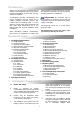
1.3 Clearance to Combustibles.
Minimum clearance to combustibles are shown
in Figure 2. Refer to table 1 below.
IMPORTANT:
The stated clearance to combustibles
represents a surface temperature of 90°F
(50° C) above room temperature.
WARNING:
Minimum clearance from the heater must be maintained from vehicles parked below heater.
In all situations, clearances to combustibles must be maintained. Signs should be posted in
storage areas to specify maximum stacking height to maintain required clearance to
combustibles. Such signs must either be posted adjacent to the heater thermostats or in the
absence of such thermostats in a conspicuous location.
Refer to mounting clearance tables.
* distance with end caps fitted.