Form I-VPS (Version B) INSTALLATION / OPERATION / MAINTENANCE Applies to: Model VPS 120V 60Hz Gas-Fired, Tubular, Radiant, Low-Intensity Infrared Heater Model VPS Burner/Control Box with 20 - 80 ft Tube/Reflector Length Part No.
Introduction. Welcome to the new range of powered infra-red heaters. Local regulations may vary and it is the installer’s responsibility to ensure that such regulations are satisfied. heaters specified in these instructions, due care and attention is required to ensure that working at height regulations are adhered to.
F. installed in accordance with the Standard for Parking Structures, ANSI/NFPA 88A, or the Standard for Repair Garages, ANSI/NFPA 88B, or the Canadian Natural Gas and Propane Installation Code, CSA B149.1, and are so marked. Ensure that minimum clearances will be maintained to vehicles parked below the heater. purpose made to sound engineering practice or supplied by others. The standard heaters are approved for installations between 0 - 2000ft (0 610m) for the US and 0 - 4500 ft (1370m) for Canada.
Minimum clearance to combustibles are shown in Figure 2. Refer to table 1 below. Building material with a low heat tolerance (such as plastics, vinyl siding, canvas, tri-ply, etc.) may be subject to degradation at lower temperatures. IMPORTANT: The stated clearance to combustibles represents a surface temperature of 90°F (50°C) above room temperature. It is the installer’s responsibility to assure that adjacent materials are protected from degradation. 1.3 Clearance to Combustibles.
B 5 E C1 Service distance Above Burner End view. Side vented A Side unvented Above Reflector Burner end. C2 Below heater B B1 Above outlet unvented End unvented D1 Outlet end. C3 Ensure that there is adequate provision in the building for combustion and ventilation air supply. Installation must meet minimum requirements and appliciable applicable codes. WARNING! . D2 Return end on U tube heater 0° to 55° A Angled view. Figure 2 Clearance to Combustibles.
1.4 Figure 3. Correct orientation of Ball Valve Gas Connection and Supply WARNING: Before installation, check that the local distribution conditions, nature of gas and pressure, and adjustment of the appliance are compatible. Gas Flow The gas connection on the heater is ½” N.P.T internal thread. Gas Flow Injector sizes and manifold pressure for the burners are shown in the table 4. The gas supply piping and connections must be installed so that the minimum pressure stated is achieved.
* Connector must be certified for use on a radiant tube type infrared heater and must comply with Standard for Connectors for Gas Appliances, ANSI Z21.24/CSA 6.10 or with the Standard for Elastomeric Composite Hose and Hose Couplings for Conducting Propane and Natural Gas, CAN/CGA 8.1.
Figure 5a. Single and Multiple Heater Installations 120V Control G T BK 120V 60Hz 1 Ph Supply circuit 110V 120V Thermostat Thermostat Other burners Burner 1 W BK GND L2 L1 (HOT) W KEY: G-GREEN W-WHITE BK-BLACK BK G other burners Figure 5b. Single Heater Installations 24V Control BK L1 METHOD:Cut and strip pink cables linking terminals W1 and R Attach thermostat wires using suitable wire nuts.
Figure 6. Internal Burner Wiring Diagram.
1.6 Vent Requirements and Details 1.6.1 Unvented units Heaters may be installed without a vent providing the governing building codes are met and consideration is properly given to possibilities of condensation on cold surfaces. Installation shall meet the requirements when unvented: • • following Natural or mechanical means shall be provided to supply and exhaust at least 4 CFM per 1000 BTU per hour input of installed heaters. Combustion gasses shall not impinge on combustible materials.
Figure 7.a Vertical Venting. CODE APPROVED VENT THROUGH ROOF ROOF SEAL APPROVED CAT III VENT PIPE ALUMINUM SUPPLIED BY OTHERS 4" (101mm) O.D. OR 6" (152mm) O.D. FLUE 12'-0" (3.66m) 12'-0" (3.66m) (APPROXIMATE MAXIMUM DIMENSIONS) SEAL JOINTS WITH HIGH TEMPERATURE SILICONE III ADAPTER 4" (101mm) TO 6" (152mm) DIA.CAT ALUMINUM ADAPTER REQUIRED ONLY FOR 6" (152mm) DIA. VENT END OF RADIANT TUBE Figure 7.b Horizontal Venting.
1.8 Technical Details - Table 5 1 No of Injectors Gas Connection ½” N.P.T Electrical Supply 120 volt 1 phase 60Hz 4” or 6” (101mm or 152mm) Vent size (in) 120 volt 1 phase 60Hz Unitary Fan Motor Details 1.2A MAX Current Rating Electronic Program Start up with Spark Ignition Ignition Natural Gas LP Gas Min. Heater Length Max. Heater Length Min. Heater Length Max. Heater Length BTU/Hr BTU/Hr S ft (m) S ft (m) U ft (m) U ft (m) 60 60,000 60,000 20 (6.1) 40 (12.1) 20 (6.1) 40 (12.
Natural Gas Combustion Fan Details Burner Rating Fan Type LP Gas Pressure Switch Orifice Part No. Part No. Combustion Fan Details Fan Type 269923 269925 80 269922 269925 270476 125 269923 269927 150 269926 170 269930 270475 200 Burner Rating 270476 270386 U40 60 ● 80 ● Part No. Part No. 269928 270386 270425 269933 270475 269938 U60 Burner Head 269931 270387 269937 N/A U Tube U20 Pressure Switch Orifice Part No.
2. Assembly Instructions. PLEASE READ this section prior assembly to familiarize yourself with components and tools you require at various stages of assembly. Carefully open packaging and check the contents against parts and check list. to the the the the Please ensure that all packaging is disposed of in a safe environmentally friendly way. For your own safety we recommend the use of safety boots and leather faced gloves when handling sharp or heavy items.
• Type ‘F’ are fixed reflector brackets. 2.2.4 Couplers The couplers are used for joining radiant tubes and U or L bends. Slide the coupler over the tube ensuring that the screw stop has butted up to the tube ends. Using the 9/16” wrench to tighten the bolts. 2 x SCREWS TIGHTENED TO FIX REFLECTOR • At this point raise the tube assembly into position and suspend from previously fixed chains (Working Load 100lb).
H F REFLECTORS F S BURNER ASSEMBLY Typical usage of optional bend kits: Corner reflector 90° Bend Elbow End Caps End Cap 2.2.6 End Caps (optional) Corner reflectors (optional) Corner reflectors kit Position an end cap beneath the reflector profile (where required) with the end cap flanges facing inwards. Fasten to reflector using the four ’Z’ clips. 16” crs 2.2.7 Bend(s) (where fitted) The heater can be installed with 1 or 2 90° bends or a 180° U bend.
Bends must be fitted at a distance of at least 50% of the total heat exchanger e.g. for a 60ft long heater, the closest to the burner a bend can be is 30ft. Figure . 8.
4" SUSPENSION BRACKET 12.6" ref 6" "A" VIEW ON "A" TUBE STRAP REFLECTOR TUBE STRAP DETAIL F DETAIL S SLIDING REFLECTOR BRACKET G FIXED REFLECTOR BRACKET SUPPLIED NUT & BOLT REFLECTOR DETAIL 2 x SCREWS MIN 1/8" GAP TO ALLOW REFLECTOR TO SLIDE H TURBULATOR DETAIL PT. NO.
12.
"A" 6" TUBE STRAP TUBE STRAP REFLECTOR DETAIL F DETAIL S SLIDING REFLECTOR BRACKET G FIXED REFLECTOR BRACKET SUPPLIED NUT & BOLT REFLECTOR DETAIL TUBE & REFLECTOR SUSPENSION BRACKET 2 x SCREWS MIN 1/8" GAP TO ALLOW REFLECTOR TO SLIDE H 6" REFLECTOR OVERLAP 2 x SCREWS TIGHTEN TO FIX REFLECTOR RADIANT TUBE DETAIL G BURNER INSERT NAT GAS ONLY SEE DETAIL F COUPLER *(HIGH TEMP COUPLER MODELS 38/45) VIEW ON "A" 4" 10' 3" REFLECTORS TYPICAL OF 4 DISTANCE BETWEEN SUSPENSION POINTS NO T
"A" TUBE STRAP TUBE STRAP DETAIL F DETAIL S SLIDING REFLECTOR BRACKET G FIXED REFLECTOR BRACKET SUPPLIED NUT & BOLT REFLECTOR DETAIL 2 x SCREWS MIN 1/8" GAP TO ALLOW REFLECTOR TO SLIDE H 2 x SCREWS TIGHTEN TO FIX REFLECTOR RADIANT TUBE DETAIL F COUPLER (HT COUPLER MODELS 50 & 60) 6" REFLECTOR OVERLAP G TUBE & REFLECTOR SUSPENSION BRACKET * HT COUPLER ON MODELS 38, 45, 50 & 60 BURNER INSERT SEE DETAIL REFLECTOR VIEW ON "A" 6" 4" 10' 3" REFLECTORS TYPICAL OF 5 DISTANCE BETWEEN
6" 4" "A" VIEW ON "A" TUBE STRAP REFLECTOR HT COUPLER ON ALL MODELS 10' 3" REFL'S TYPICAL OF 6 DISTANCE BETWEEN SUSPENSION G POINTS NOT TO EXCEED 12' TUBE STRAP DETAIL F DETAIL S SLIDING REFLECTOR BRACKET G FIXED REFLECTOR BRACKET SUPPLIED NUT & BOLT REFLECTOR DETAIL TUBE & REFLECTOR SUSPENSION BRACKET S 6" OVERLAP 2 x SCREWS MIN 1/8" GAP TO ALLOW REFLECTOR TO SLIDE H F *HT COUPLERS MODELS 50 & 60 6" OVERLAP G 2 x SCREWS TIGHTEN TO FIX REFLECTOR RADIANT TUBE DETAIL FIRST S
6" 4" "A" VIEW ON "A" TUBE STRAP REFLECTOR HT COUPLER ON ALL MODELS TUBE STRAP G DETAIL F DETAIL S SLIDING REFLECTOR BRACKET DETAIL FIXED REFLECTOR BRACKET SUPPLIED NUT & BOLT REFLECTOR G TUBE & REFLECTOR SUSPENSION BRACKET S 6" OVERLAP 2 x SCREWS MIN 1/8" GAP TO ALLOW REFLECTOR TO SLIDE H F HT COUPLERS MODELS 45 & 60 6" OVERLAP G 2 x SCREWS TIGHTEN TO FIX REFLECTOR RADIANT TUBE DETAIL FIRST SUSPENSION POINT TUBE STRAP RADIANT TUBE SUPPLIED NUT & BOLT DISTANCE BETWEEN SU
6" 4" 24 "A" VIEW ON "A" TUBE STRAP REFLECTOR F TUBE STRAP DETAIL F DETAIL S SLIDING REFLECTOR BRACKET G FIXED REFLECTOR BRACKET DETAIL 2 x SCREWS TIGHTEN TO FIX REFLECTOR SUPPLIED NUT & BOLT REFLECTOR H F 3" OVERLAP TUBE & REFLECTOR SUSPENSION BRACKET S 6" OVERLAP G 2 x SCREWS MIN 1/8" GAP TO ALLOW REFLECTOR TO SLIDE RADIANT TUBE DETAIL G HT COUPLER 6" OVERLAP FIRST SUSPENSION POINT TUBE STRAP RADIANT TUBE G HT COUPLER 10' 3" REFL'S TYPICAL OF 8 SUSPENSION BRACKET SUPP
VIEW ON "A" TUBE STRAP SUPPLIED NUT & BOLT REFLECTOR DETAIL F FIXED REFLECTOR BRACKET 2 x SCREWS TIGHTEN TO FIX REFLECTOR RADIANT TUBE DETAIL H FIRST SUSPENSION POINT TUBE STRAP "A" TUBE STRAP REFLECTOR 4" DISTANCE BETWEEN SUSPENSION POINTS NO TO EXCEED 12' TUBE ORIFICE SEE DETAIL 10' 3" REFLECTORS TYPICAL OF 2 DETAIL G TUBE & REFLECTOR SUSPENSION BRACKET H G 2" MINIMUM REFLECTOR OVERLAP CL STANDARD 4" COUPLER BURNER INSERT SEE DETAIL F F TURBULATOR DETAIL PT. NO.
4" 26 "A" H G VIEW ON "A" TUBE STRAP DETAIL F DETAIL S SLIDING REFLECTOR BRACKET G FIXED REFLECTOR BRACKET DETAIL 2 x SCREWS TIGHTEN TO FIX REFLECTOR SUPPLIED NUT & BOLT REFLECTOR G 2 x SCREWS MIN 1/8" GAP TO ALLOW REFLECTOR TO SLIDE RADIANT TUBE DETAIL H HT COUPLERS 38 & 45 G TUBE & REFLECTOR SUSPENSION BRACKET BURNER INSERT SEE DETAIL TUBE STRAP REFLECTOR TUBE ORIFICE SEE DETAIL 10' 3" REFLECTORS TYPICAL OF 4 DISTANCE BETWEEN SUSPENSION POINTS NO TO EXCEED 12' * HIGH TEMP 4" C
4" 27 DISTANCE BETWEEN SUSPENSION POINTS NO TO EXCEED 12' H "A" VIEW ON "A" TUBE STRAP REFLECTOR TUBE STRAP DETAIL F DETAIL S SLIDING REFLECTOR BRACKET G FIXED REFLECTOR BRACKET DETAIL 2 x SCREWS MIN 1/8" GAP TO ALLOW REFLECTOR TO SLIDE SUPPLIED NUT & BOLT REFLECTOR F * HIGH TEMP 4" COUPLER STANDARD 4" COUPLER HT COUPLERS MODELS 50 & 60 6"-9" REFLECTOR OVERLAPS F G G 2" MINIMUM REFLECTOR OVERLAP CL S 6" REFLECTOR OVERLAPS S 169,000 170-U60 *50-U60 200,000 150,000 150-U60
4" H "A" VIEW ON "A" TUBE STRAP REFLECTOR HT COUPLER ON ALL MODELS TUBE STRAP DETAIL F DETAIL S SLIDING REFLECTOR BRACKET G FIXED REFLECTOR BRACKET DETAIL 2 x SCREWS MIN 1/8" GAP TO ALLOW REFLECTOR TO SLIDE SUPPLIED NUT & BOLT REFLECTOR F G G S * HIGH TEMP 4" COUPLER 2" MINIMUM G G REFLECTOR OVERLAP CL COUPLERS 6" REFLECTOR OVERLAPS S STANDARD 4" COUPLER HT COUPLERS 6"-9" REFLECTOR OVERLAPS F TUBE & REFLECTOR SUSPENSION BRACKET G G F 200,000 n/a 169,000 169,000 2
3. Start Up Instructions. These appliances should be commissioned by a qualified mechanical contractor. 3.1 Tools Required. The following tools and equipment are advisable to complete the tasks laid out in this manual. Leather Faced Gloves Small Flat Head Screwdriver Phillips Screwdriver ½” Wrench 3.2 Suitable alternative tools may be used. 5/32” (4mm) Allen Wrench Manometer Large Adjustable Wrenches for fitting Of Gas Flex.
Start the screwdriver turning the pressure or pressure. heater and using a suitable adjust the pressure regulator, screw clockwise to increase the counter-clockwise to decrease the Set the pressure to appropriate inches w.c. from the table of gas pressures and orifice plate dimensions for correct heater description. Switch off the power supply to the heating system. Disconnect ‘U’ tube manometer, then secure screw in pressure test nipple.
Commissioning chart Check installation has been carried out to these instructions. Ensure gas and electricity supplies are isolated. Disconnect gas hose from burner Remove burner from tube and inspect burner head. (See servicing instructions) Replace burner on tube and secure. Reconnect gas hose. Open manual valve. Check soundness. Check thermostat is set to maximum and is calling for heat. Open control housing and check that all components are securely fastened. Switch on electrical supply.
4. Servicing Instructions. These appliances should be serviced annually by a competent person to ensure safe and efficient operation. In mildly dusty or polluted conditions more frequent servicing may be required. Servicing work should be carried out by a qualified mechanical contractor. 4.1 Tools Required. Suitable alternative tools may be used. The following tools and equipment are advisable to complete the tasks laid out in this manual. 4.
burner or components attached to the burner from falling to the ground. 4.3 Burner Removal Step 1 Isolate power and gas supplies. Step 2 Unplug the power connectors. 4.4 Burner Gas Injector Servicing Step 1.a Remove the burner support casting and gasket. Step 3 Detach the gas supply as shown below, taking care to support the burner connection. Step 1.
the two screws and separating the igniter lead connectors. Step 3 Reconnect ignition leads, ground lead and silicone tube to test nipple. Refit gasket and support casting. Step 4 Refit the electrode assembly and ensure the connections are secure to prevent incorrect sparking of the spark electrode. 4.5 Burner Head and Electrode Servicing Step 1 Check the pepper pot burner head for contamination. If necessary this can be removed. See below. This can be cleaned together with the Inside of the burner head.
Step 2 Remove fan screws and unplug from burner box. 4.8 Reflector Servicing The condition of the reflectors should be noted. If necessary the reflectors can be cleaned with a mild detergent. This can significantly improve the efficiency of the appliance. 4.9 Cleaning of Vent Inspect the fresh air inlet duct and vent to ensure they are free from any blockage or obstruction. The air inlet terminal and vent terminal should be inspected to ensure they are not liable to obstruction.
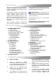
5. Spare Parts. Required Spares In order to aid troubleshooting and servicing we recommend that the components shown in this section should be stocked. Item Description Part No. Transformer (30VA) 175265 Gas Valve NG LPG 270378 270496 Flame Plates Models 60 NG & LPG 80 / 100 LPG 125 / 150 LPG 170 LPG Jet Carriers Models 60 - 150 NG 60 - 170 LPG Model 170/200 NG Note: Any spare part components that are not approved by the manufacturer could invalidate the approval of the appliance and the warranty.
6. Troubleshooting Guide. START Ensure gas & electricity supplies are enabled. Turn any external timer to call for heat (if fitted). Does the Power On light illuminate? NO Is there power to the burner? YES CHECK: 1. Transformer 2. Integrity of wiring connections. 3. Light. NO CHECK: 1. Operation of any timer or control. 2. External fuses. 3. Supply Voltage is 120VAC 60Hz YES Set thermostat to call for heat at maximum setting Does the fan run? Is there power to the fan? NO YES CHECK: 1.
To aid in the trouble shooting process the UT controller has a LED flash code diagnostic sequence: Steady Off Steady On 1 Flash 2 Flash 3 Flash 4 Flash 5 Flash 6 Flash No control Power Power Applied, Control OK Combustion Pressure Switch Open With Blower On Combustion Pressure Switch Closed With Blower Off Lockout From The Three Ignition Trials Lockout From Five Flame Losses Control Hardware Fault Detected Lockout From Five Pressure Switch Losses
7. Replacing Parts. Turn off gas and any electrical supplies to the heater before starting repair work. 7.1 Burner Controller Replacement 7.2 Air Pressure Switch Replacement Step 1 Open left hand door. Disconnect the two silicone tubes from the pressure switch. Step 1 Loosen screw in burner lid and open the right hand burner access door. Step 2 Disconnect burner controller from the wiring harness. Step 2 Remove the two screws as shown below. Step 3 Disconnect the Spark Lead from burner controller.
7.3 Gas Valve Replacement Step 1 Remove the burner assembly as described in the Servicing Sections. Step 6 Detach the two screws holding the front of the gas valve. Step 2 Open the right hand access door and detach the burner controller from the wiring harness. Step 7 Remove the four screws holding the rear burner plate in position. Step 3 Open the left hand access door and detach the silicon hoses from the air pressure switch. Step 8 Remove the rear plate.
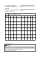
Propane Gas & Propane Altitude Conversion Kit 270619 270620 270621 270622 270623 270627* 270628** Natural Gas Altitude Conversion Kit 270630 270630 270631 270632 270633 270634 270635 270613 Combustion Air inlet Kit * Burner de-rated when converted to propane ** Burner de-rated when converted to propane. Not for use at altitude. 200 170 150 125 100 80 60 BURNER Rating. 270611 Aluminized Steel End Cap Kit (1Pair) 270277 90° Elbow Kit (1 Off) 270276 180° U-Bend Kit 7.
Notes.
Notes.
8. User & Operating Instructions. Radiant tubular infrared heaters are designed for overhead heating of industrial and commercial buildings. Individual heating units are suspended from the roof. 8.1 1. This appliance must only be installed by qualified installer in accordance with the requirements of local and National Codes. 2. This appliance must be grounded in accordance with the National Electrical Code ANSI/NFPA No.70 or Canadian Codes. 3.