
Venting Instructions

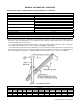
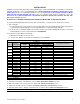
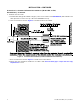
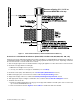
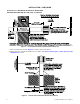
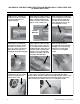
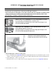
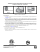
Table Of Contents
- VENTING INSTRUCTIONS FOR UNIT HEATERS (MODEL UBX: STANDARD POWER VENT BLOWER TYPE AND MODEL UDX: STANDARD POWER VENT FAN TYPE)
- GENERAL INFORMATION
- INSTALLATION
- Instructions for Commercial/Industrial Installations (Model UBX or UDX, All Unit Sizes)
- Instructions for Residential Installations (Model UDX, Unit Sizes 030, 045, 060, 075, 100, 125)
- Instructions for Commercial/Industrial or Residential Installations (Model UDX, Unit Sizes 030, 045, 060, 075, Vertical Category I)
- APPENDIX A: INSTRUCTIONS FOR ATTACHING DOUBLE-WALL TYPE B VENT PIPE TO SINGLE-WALL PIPE
- APPENDIX B: INSTRUCTIONS FOR INSTALLING FLEX-L BRANDCATEGORY III VENT PIPE
- FIGURES
- Figure 1. Roof Slope and Pitch
- Figure 2. Horizontal Vent Terminal (Commercial/Industrial Installations)
- Figure 3. Vertical Vent Terminal (Commercial/Industrial Installations)
- Figure 4. Horizontal Vent Terminal (Residential Installations)
- Figure 5. Vertical Vent Terminal (Residential Installations)
- Figure B1. Reducer and Vent Cap
- TABLES

APPENDIX B: INSTRUCTIONS FOR INSTALLING FLEX-L BRAND
CATEGORY III VENT PIPE—CONTINUED
Figure B1. Reducer and Vent Cap
2. Run vent pipe:
a. Determine vent length in accordance with residential or commercial/industrial vent length requirements in
Installation section.
b. If using 4- to 3-inch (102- to 76-mm) reducer, follow vent pipe manufacturer’s instructions to attach straight
piece of 3-inch diameter horizontal pipe or elbow in any direction above horizontal. If using 4-inch (102-mm)
diameter 12-inch (305-mm) long adapter pipe, follow vent pipe manufacturer’s instructions to attach elbow in
any direction above horizontal or straight horizontal pipe.
c. Follow pipe manufacturer’s instructions to connect vent pipe sections and install vent pipe run—length of vent
must not exceed maximum allowed for heater being installed.
d. Extend vent pipe through wall or roof to outdoors. Approved clearance thimble is required when flue pipe
extends through combustible materials. Follow requirements of pipe and thimble manufacturer. Be sure to
comply with local and national codes when selecting vent terminal location. Vent pipe installer is responsible
for following manufacturer’s instructions and complying with all applicable codes.
3. Attach vent cap ( see Figure B1, DETAIL C):
a. Use option CC1 or CC21 vent cap or Novavent #2NVTB4 vent cap.
b. Slide vent cap collar into vent pipe.
c. Drill three evenly-spaced 1/8-inch holes around end of vent pipe through pipe and vent cap and secure joint
using sheet metal screws.
Silicone bead
Sheet metal screw
Vent cap
DETAIL A
DETAIL B DETAIL C
A
G
E
N
C
Y
P
R
O
C
E
S
S
S
T
A
R
T
-
U
P
P
R
O
D
U
C
T
C
U
S
T
O
M
E
R
W
A
R
R
A
N
T
Y
C
O
N
V
E
R
G
E
N
T
Q
U
A
L
I
T
Y
S
Y
S
T
E
M
CQS
CQS
Specifications and illustrations subject to change without notice or incurring obligations.
©2021 Nortek Global HVAC LLC, O’Fallon, MO.
All rights reserved.
CP-UBX-UDX-VENT (03-21) 1034631-0