
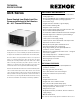
UDX Submittal


5
J
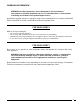
Access Panel clearance is required for service clearance to controls
K
Suspend the heater so that the bottom is a minimum of 5’ (1.5M) above the floor.
L
Rear clearance is required for air movement. Rear clearance should be measured from the fan motor.
Size (in) A B C D E F G H J K M N P Q R S T
30, 45
13 3/4
27
10
13
13/16
29 3/4
25 9/16
6
5 15/16
3 1/2
3 11/32 17 3/8 1 9/16 4 9/32 13 9 9/16
3 3/4
2 15/16
60
16 3/4 13
27
8 11/16 6 4 1/16
75
27 5/8
100
24 3/4 21 34 9/32 15 5/16 8 29/32 5 15/32
125
150, 175,
200
20 1/8
38 3/16
16
23
48 7/16
40
9 5/8
8 5/16
5 3/8
6 1/2
25
11/16
1 13/32 8 1/8 22 3/16
16 3/8
5 1/2 4 1/4
225, 250
26 1/8 22 13 1/16 9 8 1/16 4 5/16
300, 350,
400
34 1/8 41 30
48
29/32
17 1/16 8 1/2
11
13/16
7 5/16
27
11/16
16 1/4 11 9/16 16 3/16
Size (mm) A B C D E F G H J K M N P Q R S T
30,45
349
686
254
351
756
649
152
151
89
85 441 40 109 330 243
95
75
60
425 330
831
221 152 103
75
810
100
629 533 871 389 226 139
125
150, 175,
200
511
970
406
584
1230
1016
244
211
137
165 652
36 206 564
416
140 108
225,250
664 559 332 229 205 110
300, 350,
400
867 1041 762 1243 433 216 300 186 703 413 294 114
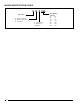
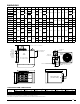
DIMENSIONS
Size
Top Flue Connector Access Panel
J
Non-Access Side Bottom
K
Rear
L
inches mm inches mm inches mm inches mm inches mm inches mm
30-125 1 25 6 152 18 457 1 25 1 25 18 457
150-400 4 102 6 152 18 457 2 51 1 25 18 457
CLEARANCES FROM COMBUSTIBLES
A
B
D
C
FRONT
VIEW
E
F
RIGHT SIDE VIEW
(ACCESS PANEL)
Q
N
M
R
P
3/8-16 FEMALE THREAD
- ALL SUSPENSION POINTS
M AND N - HANGER DIMENSIONS
FOR BOTH 2-PT AND 4-PT SUSPENSION
TOP
VIEW
J
G
K
H
S
T
THERMOSTAT
CONNECTION
LINE VOLTAGE INLET
(CONNECTS AT CIRCUIT BOARD)
VENT COLLAR
EXTERNAL GAS CONNECTION
COMBUSTION
AIR INLET
REAR
VIEW
R - HANGER DIMENSION
FOR 2-PT SUSPENSION
P AND Q -
HANGER
DIMENSIONS
FOR 4-PT
SUSPENSION
(4-PT IS
REQUIRED IF
INSTALLING
OPTIONAL
NOZZLE.)
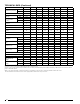
DIMENSIONS - MODELS UDX AND UDZ
UNIT SIZE
A
B
C
D
E
F
G
H
J
K
M
N P
Q
R
S
T
INCHES (
1/16) (mm (
2))
030, 045
13 3/4
(349)
27
(686)
10
(254)
13 13/16
(351)
29 3/4
(756)
25 9/16
(649)
6
(152)
5 15/16
(151)
3 1/2
(89)
3 11/32
(85)
17 3/8
(441)
1 9/16
(40)
4 9/32
(109)
13
(330)
9 9/16
(243)
3 3/4
(95)
2 15/16
(75)
060
16 3/4
(425)
13
(330)
32 23/32
(831)
8 11/16
(221)
6
(152)
4 1/16
(103)
075
31 29/32
(810)
100
24 3/4
(629)
21
(533)
34 9/32
(871)
15 5/16
(389)
8 29/32
(226)
5 15/32
(139)
125
150,175,200
20 1/8
(511)
38 3/16
(970)
16
(406)
23
(584)
48 7/16
(1230)
40
(1016)
9 5/8
(244)
8 5/16
(211)
5 3/8
(137)
6 1/2
(165)
25 11/16
(652)
1 13/32
(36)
8 1/8
(206)
22 3/16
(564)
16 3/8
(416)
5 1/2
(140)
4 1/4
(108)
225,250
26 1/8
(664)
22
(559)
13 1/16
(332)
9
(229)
8 1/16
(205)
4 5/16
(110)
300,350,400
34 1/8
(867)
41
(1041)
30
(762)
48 29/32
(1243)
17 1/16
(433)
8 1/2
(216)
11 13/16
(300)
7 5/16
(186)
27 11/16
(703)
16 1/4
(413)
11 9/16
(294)
4 1/2
(114)
REV.
REVISION RECORD
DATE
BY
ENGR.
ECM
UDX & UDZ GA
DRAWING
UDX-UDZ_GA
SHEET
1
OF
1
SCALE: N.T.S
DRAWING No:
TITLE:
REVISION
DO NOT SCALE DRAWING
MATERIAL:
DATE
DEBUR AND BREAK
SHARP EDGES
FINISH:
DRAWN
-
SHEET SIZE:
A2
See Parts
CHK'D
PROJECT No.
-
-
HCL
12/29/2020
WEIGHT:
lbs
UNLESS OTHEWISE SPECIFIED
DIMENSIONS ARE IN INCHES
TOLERANCE UNLESS OTHERWISE
SPECIFIED FOR HOLE DIAMETERS
UP TO .250 .005, 250-1.000 .010,
OVER 1.000 .015
TOLERANCE UNLESS OTHERWISE
SPECIFIED FOR LINEAR
DIMENSIONS
AND SQUARENESS IS .04
TOLERANCE UNLESS OTHERWISE
SPECIFIED FOR ANGLE IS 1.5
Third Angle
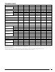
Size 150 175 200 225 250 300 350 400
Input Heating Capacity
BTUH 150,000 175,000 200,000 225,000 250,000 300,000 350,000 400,000
kw/h 43.9 51.2 58.6 65.9 73.2 87.8 102.5 117.1
Thermal Efficiency (%) 83 83 83 83 83 83 83 83
Output Heating
Capacity
C
BTUH 124,500 145,250 166,000 186,750 207,500 249,000 290,500 332,000
kw/h 36.4 42.5 48.6 54.7 60.8 72.9 85.1 97.2
Gas Connection
(inches)
D
Natural 1/2 1/2 1/2 3/4 3/4 3/4 3/4 3/4
Propane 1/2 1/2 1/2 3/4 3/4 3/4 3/4 3/4
Vent Connection Size
E
(inches
diameter)
5 5 5 5 5 6 6 6
Control Amps (24 volt) 1.0 1.0 1.0 1.0 1.0 1.0 1.0 1.0
Full Load Amps (115 volt) 3.8 3.8 4.6 7.5 7.5 11.0 11.0 11.0
Maximum Over Current Protection
(115V)
F
15 15 15 15 15 20 20 20
Normal Power Consumption (watts) 392 392 491 747 747 1086 1086 1086
Discharge Air Temperature Rise (°F) 60 60 60 60 60 60 60 60
Air Volume
CFM 1921 2242 2562 2882 3202 3843 4483 5123
M
3
/minute 54.4 63.5 72.5 81.6 90.7 108.8 126.9 145.1
Discharge Air Opening
Area
ft
2
2.56 2.56 2.56 3.51 3.51 4.79 4.79 4.79
M
2
0.24 0.24 0.24 0.33 0.33 0.45 0.45 0.45
Output Velocity
FPM 752 877 1003 820 911 802 936 1069
M/minute 229 267 306 250 278 244 285 326
Fan Motor HP
G
Open 1/6 1/6 1/6 1/4 1/4 1/2 1/2 1/2
Enclosed 1/4 1/4 1/4 1/4 1/4 1/2 1/2 1/2
Fan Motor RPM 1050 1050 1050 1050 1050 1050 1050 1050
Fan Diameter (inches) 18 18 18 20 20 24 24 24
Sound Level dba @ 15 ft 51 52 53 56 56 59 61 62
Approximate Net
Weight
lbs 178 193 193 211 223 277 303 316
kg 81 88 88 96 101 126 137 143
Approximate Ship
Weight
lbs 206 221 221 247 259 323 348 360
kg 93 100 100 112 117 147 158 163