
UDX Installation Manual
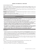
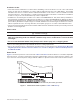
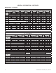
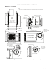
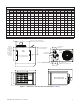
Table Of Contents
- UNIT HEATER INSTALLATION/OPERATION/MAINTENANCE (MODEL UBX: STANDARD POWER VENT BLOWER TYPE, MODEL UBZ: SEPARATED-COMBUSTION BLOWER TYPE, MODEL UDX: STANDARD POWER VENT FAN TYPE, AND MODEL UDZ: SEPARATED-COMBUSTION FAN TYPE)
- TABLE OF CONTENTS
- GENERAL INFORMATION
- INSTALLATION
- CONTROLS
- OPERATION
- ADJUSTMENTS
- MAINTENANCE
- Service Checklist
- Maintenance Procedures
- Burner Maintenance
- Burner Orifice Maintenance
- Heat Exchanger Maintenance
- Ignition System Maintenance
- Maintenance of Fan Motor, Fan Blades, and Fan Guard
- Venter Motor and Wheel Assembly Maintenance
- Operating Gas Valve Maintenance
- Pressure Switch Maintenance
- High Temperature Limit Control Maintenance
- Flame Rollout Switch Maintenance (Model UDZ Unit Sizes 030–125 Only)
- Interlock Door Switch Maintenance (Models UBZ and UDZ Only)
- Transformer Maintenance
- Disconnect Switch Replacement (Models UBZ and UDZ Only)
- Vent or Vent/Combustion Air System Maintenance
- TROUBLESHOOTING
- INSTALLATION RECORD (TO BE COMPLETED BY INSTALLER)
- FIGURES
- Figure 1. Heater Throw Patterns (Refer to Table 2 and Table 3)
- Figure 2. Dimensions—Models UBX and UBZ (Refer to Table 4)
- Figure 3. Dimensions—Models UDX and UDZ (Refer to Table 5)
- Figure 4. Confined Space Combustion Air Openings (Refer to Table 8)
- Figure 5. Plugging Unused Suspension Points (Models UBZ and UDZ Only)
- Figure 6. Option CK10 Hanger Kit
- Figure 7. Option CK22 Hanger Kit
- Figure 8. Heater Suspension Using Field-Supplied Threaded Rods
- Figure 9. Gas Connections
- Figure 10. Supply Wiring Entrance and Control Connection Terminal Strip
- Figure 11. Circuit Board (DSI Control Module)
- Figure 12. Component Locations (Typical)
- Figure 13. Gas Valve ON/OFF Control
- Figure 14. Pressure Switch
- Figure 15. Gas Valves
- Figure 16. Typical Burner Assembly
- Figure 17. Ignitor Spark Gap
- Figure 18. Fan Blade Positioning and Spacing
- Figure 19. Venter Motor and Wheel Assembly
- Figure 20. Replaceable Components
- Figure 21. DSI Control Module Troubleshooting Flowchart
- TABLES
- Table 1. Related Technical Manuals Available from Factory Distributor
- Table 2. Heater Throw Distances with Standard Horizontal Louvers at Mounting Heights of 5 to 18 Feet
- Table 3. Heater Throw Distances with Standard Horizontal Louvers at Mounting Heights of 1.5 to 5.5 Meters
- Table 4. Dimensions—Models UBX and UBZ
- Table 5. Dimensions—Models UDX and UDZ
- Table 6. Clearances to Combustibles
- Table 7. Unit Weights
- Table 8. Determining Confined Space Combustion Air Requirements
- Table 9. Technical Data for UBX and UBZ Models (Unit Sizes 030–125)
- Table 10. Technical Data for UBX and UBZ Models (Unit Sizes 150–400)
- Table 11. Technical Data for UDX and UDZ Models (Unit Sizes 030–125)
- Table 12. Technical Data for UDX and UDZ Models (Unit Sizes 150–400)
- Table 13. Field-Installed Options
- Table 14. Gas Supply Line Sizes
- Table 15. Gas Connection Sizes
- Table 16. Pressure Switch Settings
- Table 17. Operating Sequence (Normal Heat Cycle)
- Table 18. Operating Sequence (Abnormal Heat Cycle)
- Table 19. Fault Modes
- Table 20. Required Manifold (Outlet) Gas Pressure
- Table 21. Inputs and Capacities by Elevation in US
- Table 22. Inputs and Capacities by Elevation in Canada
- Table 23. Fan Blade Spacing
- Table 24. General Troubleshooting
- Table 25. Circuit Board (DSI Control Module) Display Codes

7
UBX-UBZ-UDX-UDZ-IOM (03-22) 1034344-C
Mounting Height Requirements
⚠ WARNING ⚠
If touched, the vent pipe and internal heater surfaces that are accessible from outside the heater
will cause burns. Suspend the heater a minimum of 5 feet (1.5 meters) above the floor.
• For best results, the heater should be mounted with certain rules in mind. In general, a unit should be located 8 to
12 feet (2.4 to 3.7 meters) above the floor. Units should always be arranged to blow toward or along exposed wall
surfaces, if possible. Where two or more units are installed in the same room, a general scheme of air circulation
should be maintained for best results.
• Suspended heaters are most effective when located as close to the working zone as possible, and this fact should
be kept in mind when determining the mounting heights to be used. However, care should be exercised to avoid
directing the discharged air directly on the room occupants.
• Partitions, columns, counters, or other obstructions should be taken into consideration when locating the unit heater
so that a minimum quantity of airflow will be deflected by such obstacles.
• When units are located in the center of the space to be heated, the air should be discharged toward the exposed
walls. In large areas, units should be located to discharge air along exposed walls with extra units provided to
discharge air in toward the center of the area.
• At those points where infiltration of cold air is excessive, such as at entrance doors and shipping doors, it is
desirable to locate the unit so that it will discharge directly toward the source of cold air from a distance of 15 to
20 feet (4.6 to 6.1 meters).
• For a location where dirt, dust, or other airborne contaminants are present in the indoor environment, a separated-
combustion unit that uses outside air for combustion is recommended. Using a separated-combustion unit reduces
the buildup of contaminants on the burner. Any buildup on the burner adversely affects the combustion process.
Hazards of Chlorine
The presence of chlorine vapors in the combustion air of gas-fired heating equipment presents a potential corrosion
hazard for separated-combustion heaters with regard to the combustion air inlet. Chlorine is usually found in the form
of freon or degreaser vapors. When chlorine is exposed to flame, it will precipitate from the compound and go into
solution with any condensation that is present in the heat exchanger or associated parts. The result is hydrochloric
acid, which readily attacks all metals including 300 grade stainless steel. Care should be taken to separate these
vapors from the combustion process. This may be done by wise location of the unit vent and combustion air terminals
with regard to exhausters or prevailing wind directions. Chlorine is heavier than air. Keep these facts in mind when
determining installation location of the heater in relation to building exhaust systems.
Dimensions
Unit dimensions are shown in Figure 2 and Figure 3 and listed in Table 4 and Table 5.