
Install Instructions
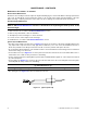
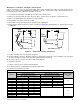
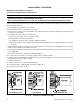
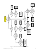
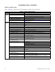
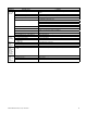
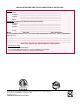
Table Of Contents
- UNIT HEATER INSTALLATION/OPERATION/MAINTENANCE: (MODEL UBX: STANDARD POWER VENT BLOWER TYPE, MODEL UBZ: SEPARATED-COMBUSTION BLOWER TYPE, MODEL UDX: STANDARD POWER VENT FAN TYPE, MODEL UDZ: SEPARATED-COMBUSTION FAN TYPE)
- TABLE OF CONTENTS
- GENERAL INFORMATION
- INSTALLATION
- CONTROLS
- OPERATION
- ADJUSTMENTS
- MAINTENANCE
- Service Checklist
- Maintenance Procedures
- Burner Maintenance
- Burner Orifice Maintenance
- Heat Exchanger Maintenance
- Ignition System Maintenance
- Maintenance of Fan Motor, Fan Blades, and Fan Guard
- Venter Motor and Wheel Assembly Maintenance
- Operating Gas Valve Maintenance
- Pressure Switch Maintenance
- High Temperature Limit Control Maintenance
- Flame Rollout Switch Maintenance (Model UDZ Unit Sizes 030–125 Only)
- Interlock Door Switch Maintenance (Models UBZ and UDZ Only)
- Transformer Maintenance
- Disconnect Switch Replacement (Models UBZ and UDZ Only)
- Vent or Vent/Combustion Air System Maintenance
- TROUBLESHOOTING
- INSTALLATION RECORD (TO BE COMPLETED BY INSTALLER)
- FIGURES
- Figure 1. Heater Throw Patterns (Refer to Table 2 and Table 3)
- Figure 2. Dimensions—Models UBX and UBZ (Refer to Table 4)
- Figure 3. Dimensions—Models UDX and UDZ (Refer to Table 5)
- Figure 4. Confined Space Combustion Air Openings (Refer to Table 8)
- Figure 5. Plugging Unused Suspension Points (Models UBZ and UDZ Only)
- Figure 6. Option CK8 or CK10 Hanger Kit
- Figure 7. Option CK22 Hanger Kit
- Figure 8. Heater Suspension Using Field-Supplied Threaded Rods
- Figure 9. Gas Connections
- Figure 10. Supply Wiring Entrance and Control Connection Terminal Strip
- Figure 11. Circuit Board (DSI Control Module)
- Figure 12. Component Locations (Typical)
- Figure 13. Gas Valve ON/OFF Control
- Figure 14. Pressure Switch
- Figure 15. Gas Valves
- Figure 16. Typical Burner Assembly
- Figure 17. Ignitor Spark Gap
- Figure 18. Fan Blade Positioning and Spacing
- Figure 19. Venter Motor and Wheel Assembly
- Figure 20. Replaceable Components
- Figure 21. DSI Control Module Troubleshooting Flowchart
- TABLES
- Table 1. Related Technical Manuals Available from Factory Distributor
- Table 2. Heater Throw Distances with Standard Horizontal Louvers at Mounting Heights of 5 to 18 Feet
- Table 3. Heater Throw Distances with Standard Horizontal Louvers at Mounting Heights of 1.5 to 5.5 Meters
- Table 4. Dimensions—Models UBX and UBZ
- Table 5. Dimensions—Models UDX and UDZ
- Table 6. Clearances to Combustibles
- Table 7. Unit Weights
- Table 8. Determining Confined Space Combustion Air Requirements
- Table 9. Technical Data for UBX and UBZ Models (Unit Sizes 030–125)
- Table 10. Technical Data for UBX and UBZ Models (Unit Sizes 150–400)
- Table 11. Technical Data for UDX and UDZ Models (Unit Sizes 030–125)
- Table 12. Technical Data for UDX and UDZ Models (Unit Sizes 150–400)
- Table 13. Field-Installed Options
- Table 14. Gas Supply Line Sizes
- Table 15. Gas Connection Sizes
- Table 16. Pressure Switch Settings
- Table 17. Circuit Board (DSI Control Module) Display Codes
- Table 18. Operating Sequence (Normal Heat Cycle)
- Table 19. Operating Sequence (Abnormal Heat Cycle)
- Table 20. Fault Modes
- Table 21. Required Manifold (Outlet) Gas Pressure
- Table 22. Inputs and Capacities by Elevation in US
- Table 23. Inputs and Capacities by Elevation in Canada
- Table 24. Fan Blade Spacing
- Table 25. General Troubleshooting

46
I-UBX-UBZ-UDX-UDZ (04-21) 1034344-0
TROUBLESHOOTING—CONTINUED
General Troubleshooting
Refer to Table 25 for general troubleshooting symptoms, probable causes, and remedies.
Table 25. General Troubleshooting
Symptom Probable Cause Remedy
Venter
motor will
not start
1. No power to unit Turn ON power and check supply fuses or circuit breaker
2. No 24V power to integrated circuit board Turn up thermostat
Check control transformer output
3. Integrated circuit board fuse blown Correct cause and replace fuse (3A, type ATC or ATO, 32VDC)
4. No power to venter motor Tighten connections at circuit board and/or motor terminals
5. Integrated circuit board defective Replace integrated circuit board
6. Defective venter motor Replace venter motor (refer to Venter Motor and Wheel Assembly
Maintenance section)
Burner will
not light
1. Manual valve not open Open manual valve
2. Air in the gas line Bleed gas line (initial startup only)
3. Gas pressure too high or too low Supply pressure should be 5–14 IN WC for natural gas or 11–14 IN WC for
propane
4. No spark Perform following:
a. Loose wire connections Ensure that all wire connections are solid
b. Transformer failure Ensure that 24V power is available
c. Incorrect spark gap Maintain spark gap at 1/8 inch
d. Spark cable shorted to ground Replace worn or grounded spark cable
e. Spark electrode shorted to ground Replace ceramic spark electrode if it is cracked or grounded
f. Burner not grounded Ensure that integrated circuit board is grounded (terminals P1–9)
g. Circuit board not grounded Ensure that integrated circuit board is grounded to furnace chassis
h. Unit not properly grounded Ensure that unit is properly field grounded to earth ground and properly phased
(L1 to hot lead L2 to neutral)
i. Integrated circuit board fuse blown Correct cause and replace fuse (3A, type ATC or ATO, 32VDC)
j. Faulty integrated circuit board If 24V power is available to integrated circuit board and all other causes have
been eliminated, replace board
5. Lockout device interrupting control
circuit by above causes
Reset lockout by interrupting control at thermostat or main power
6. Interlock door switch open
Close access door or replace switch
7. Pressure switch not closing Perform following:
Ensure that unit is properly vented
Remove obstruction(s) from vent
Replace faulty tubing to pressure switch
8. Faulty pressure switch Replace pressure switch
9. Main valve not operating Perform following:
a) Defective valve If 24V power is measured at valve connections and valve remains closed,
replace valve
b) Loose wire connections Check and tighten all wiring connections
10. Integrated circuit board does not
power main valve
Perform following:
a) Loose wire connections Ensure that all wire connections are solid
b) Flame sensor grounded Ensure that flame sensor lead is not grounded or that sensor insulation or
ceramic is not cracked—replace as required
c) Incorrect gas pressure Supply pressure should be 5–14 IN WC for natural gas or 11–14 IN WC for
propane
d) Cracked ceramic at sensor Replace sensor