
UDX Installation Manual
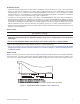
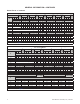
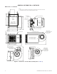
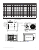
Table Of Contents
- UNIT HEATER INSTALLATION/OPERATION/MAINTENANCE (MODEL UBX: STANDARD POWER VENT BLOWER TYPE, MODEL UBZ: SEPARATED-COMBUSTION BLOWER TYPE, MODEL UDX: STANDARD POWER VENT FAN TYPE, AND MODEL UDZ: SEPARATED-COMBUSTION FAN TYPE)
- TABLE OF CONTENTS
- GENERAL INFORMATION
- INSTALLATION
- CONTROLS
- OPERATION
- ADJUSTMENTS
- MAINTENANCE
- Service Checklist
- Maintenance Procedures
- Burner Maintenance
- Burner Orifice Maintenance
- Heat Exchanger Maintenance
- Ignition System Maintenance
- Maintenance of Fan Motor, Fan Blades, and Fan Guard
- Venter Motor and Wheel Assembly Maintenance
- Operating Gas Valve Maintenance
- Pressure Switch Maintenance
- High Temperature Limit Control Maintenance
- Flame Rollout Switch Maintenance (Model UDZ Unit Sizes 030–125 Only)
- Interlock Door Switch Maintenance (Models UBZ and UDZ Only)
- Transformer Maintenance
- Disconnect Switch Replacement (Models UBZ and UDZ Only)
- Vent or Vent/Combustion Air System Maintenance
- TROUBLESHOOTING
- INSTALLATION RECORD (TO BE COMPLETED BY INSTALLER)
- FIGURES
- Figure 1. Heater Throw Patterns (Refer to Table 2 and Table 3)
- Figure 2. Dimensions—Models UBX and UBZ (Refer to Table 4)
- Figure 3. Dimensions—Models UDX and UDZ (Refer to Table 5)
- Figure 4. Confined Space Combustion Air Openings (Refer to Table 8)
- Figure 5. Plugging Unused Suspension Points (Models UBZ and UDZ Only)
- Figure 6. Option CK10 Hanger Kit
- Figure 7. Option CK22 Hanger Kit
- Figure 8. Heater Suspension Using Field-Supplied Threaded Rods
- Figure 9. Gas Connections
- Figure 10. Supply Wiring Entrance and Control Connection Terminal Strip
- Figure 11. Circuit Board (DSI Control Module)
- Figure 12. Component Locations (Typical)
- Figure 13. Gas Valve ON/OFF Control
- Figure 14. Pressure Switch
- Figure 15. Gas Valves
- Figure 16. Typical Burner Assembly
- Figure 17. Ignitor Spark Gap
- Figure 18. Fan Blade Positioning and Spacing
- Figure 19. Venter Motor and Wheel Assembly
- Figure 20. Replaceable Components
- Figure 21. DSI Control Module Troubleshooting Flowchart
- TABLES
- Table 1. Related Technical Manuals Available from Factory Distributor
- Table 2. Heater Throw Distances with Standard Horizontal Louvers at Mounting Heights of 5 to 18 Feet
- Table 3. Heater Throw Distances with Standard Horizontal Louvers at Mounting Heights of 1.5 to 5.5 Meters
- Table 4. Dimensions—Models UBX and UBZ
- Table 5. Dimensions—Models UDX and UDZ
- Table 6. Clearances to Combustibles
- Table 7. Unit Weights
- Table 8. Determining Confined Space Combustion Air Requirements
- Table 9. Technical Data for UBX and UBZ Models (Unit Sizes 030–125)
- Table 10. Technical Data for UBX and UBZ Models (Unit Sizes 150–400)
- Table 11. Technical Data for UDX and UDZ Models (Unit Sizes 030–125)
- Table 12. Technical Data for UDX and UDZ Models (Unit Sizes 150–400)
- Table 13. Field-Installed Options
- Table 14. Gas Supply Line Sizes
- Table 15. Gas Connection Sizes
- Table 16. Pressure Switch Settings
- Table 17. Operating Sequence (Normal Heat Cycle)
- Table 18. Operating Sequence (Abnormal Heat Cycle)
- Table 19. Fault Modes
- Table 20. Required Manifold (Outlet) Gas Pressure
- Table 21. Inputs and Capacities by Elevation in US
- Table 22. Inputs and Capacities by Elevation in Canada
- Table 23. Fan Blade Spacing
- Table 24. General Troubleshooting
- Table 25. Circuit Board (DSI Control Module) Display Codes
2
UBX-UBZ-UDX-UDZ-IOM (03-22) 1034344-C
TABLE OF CONTENTS
GENERAL INFORMATION ................................................................... 3
References .............................................................................. 3
Important Safety Information................................................................. 4
Certification .............................................................................. 4
Warranty ................................................................................ 4
Installation Codes ......................................................................... 5
Unit Location ............................................................................. 5
Heater Throw............................................................................. 5
Mounting Height Requirements............................................................... 7
Hazards of Chlorine........................................................................ 7
Dimensions . . . . . . . . . . . . . . . . . . . . . . . . . . . . . . . . . . . . . . . . . . . . . . . . . . . . . . . . . . . . . . . . . . . . . . . . . . . . . . 7
Clearances .............................................................................10
Weights ................................................................................10
Combustion Air Requirements ..............................................................11
Acoustical Considerations..................................................................12
Technical Data ..........................................................................12
INSTALLATION ...........................................................................16
Unpacking and Inspection..................................................................16
Pre-Installation Checklist...................................................................16
Heater Suspension .......................................................................17
Suspension of Heater with Downturn Nozzle .................................................18
Suspension of Heater Using CK10 Hanger Kit................................................18
Suspension of Heater Using Option CK22 Hanger Kit ..........................................18
Heater Suspension Using Field-Supplied Threaded Rods.......................................19
Piping Connections .......................................................................19
Gas Supply Pressure ...................................................................19
Gas Supply Piping .....................................................................19
Supply Piping Connections ..............................................................20
Electrical Connections.....................................................................21
CONTROLS ..............................................................................23
Pressure Switch .........................................................................23
High Temperature Limit Control .............................................................25
Flame Rollout Switch (UDX Model Unit Sizes 030–125)...........................................25
Interlock Door Switch (UBZ and UDZ Models) ..................................................25
Main Operating Gas Valve .................................................................25
Fan Motor ..............................................................................25
Venter Motor . . . . . . . . . . . . . . . . . . . . . . . . . . . . . . . . . . . . . . . . . . . . . . . . . . . . . . . . . . . . . . . . . . . . . . . . . . . . 25
Thermostat Options.......................................................................26
Circuit Board (DSI Control Module)...........................................................26
OPERATION .............................................................................27
Pre-Startup Checklist .....................................................................27
Startup.................................................................................27
Operating Sequences . . . . . . . . . . . . . . . . . . . . . . . . . . . . . . . . . . . . . . . . . . . . . . . . . . . . . . . . . . . . . . . . . . . . . 29
Vent System Testing ......................................................................31
Post-Startup Checklist.....................................................................32
ADJUSTMENTS...........................................................................32
Pressure Switch Replacement ..............................................................32
Measure and Adjust Manifold (Outlet) Gas Pressure .............................................33
Measure and Adjust Manifold Gas Pressure—Elevation ≤2,000 Feet (≤610 Meters) ..................33
Measure and Adjust Manifold Gas Pressure—Elevation >2,000 Feet (>610 Meters) ..................35