
UDAP/APD/UDBP Venting Requirements

Form I-UD&APD Series-V-PV (5-17), P/N 195675R20, Page 8
3.7 Vent Terminal (cont’d)
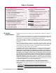
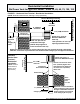
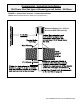
FIGURE 3 - Horizontal Vent Terminal - Commercial/Industrial Installation
(NOTE: Read all measurements; drawing is not proportional.)
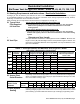
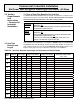
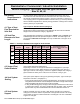
TABLE 6 - Horizontal Vent
Terminal Clearances
Maintain a clearance of 6 to 12 inches
(152-305mm) from the wall to the vent
terminal cap for stability under wind
conditions.
Products of combustion can cause
discoloration of some building
nishes and deterioration of masonry
materials. Applying a clear silicone
sealant that is normally used to
protect concrete driveways can protect
masonry materials. If discoloration is
an esthetic problem, relocate the vent
or install a vertical vent.
Structure
Minimum Clearances for Vent
Termination Location (all
directions unless specied)
Forced air inlet within 10 ft (3.1M) 3 ft (0.9M) above
Combustion air inlet of another
appliance
6 ft (1.8M)
Door, window, or gravity air inlet
(any building opening)
4 ft (1.2M) horizontally
4 ft (1.2M) below
1 ft (305mm) above
Electric meter, gas meter*, gas
regulator*,
U.S. - 4 ft (1.2M) horizontally
Gas regulator * U.S. - 3 ft (0.9M)
Adjoining building or parapet 6 ft (1.8M)
Adjacent public walkways 7 ft (2.1M) above
Grade (ground level) 1 ft (305mm) above**
*Do not terminate the vent directly above a gas meter or service
regulator.
** Consider local snow depth conditions. The vent must be at least 6”
(152mm) higher than anticipated snow depth.
Commercial / Industrial Installation
Std Power Vent fan type or blower type unit heater - All Sizes
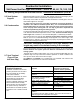
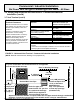
3.0 Venting Requirements and Instructions - Commercial/Industrial
Installation (cont’d)
Approved clearance thimble is required when the flue pipe extends through combustible
materials. Follow the requirements of the thimble and/or vent pipe manufacturer.
Vent Pipe
(Comply with
requirements
in 3.1 & 3.2
on page 6.)
* Follow the instructions in Addendum Section A, page 10,
to join a double-wall vent terminal section to a single-wall
vent run and to the vent cap.
Roof or Building Overhang
Parapet or Adjoining Buildings
Heaters w/Option CC1,
CC21 or Novavent
#2NVTB4 Vent
Cap - note positions
of vent cap openings
(shaded areas)
6” (152mm)
minimum
3 ft (1M)
minimum
6 ft (1.8M) minimum
Double-Wall* Vent Pipe
6” (152mm)
minimum
Pitch flue pipe dow
toward outlet 1/4” per foot
for condensate drainage
(NOTE: Slope applies to
entire horizontal vent run).
Wall