
UDAP Installation Manual

Page 10, D300519 PN 195673 R30
WARNINGS
Check the supporting structure to be used to verify that it has sufcient
load carrying capacity to support the weight of the unit. Suspend the
heater only from the threaded nut retainers or with a manufacturer
provided kit. Do NOT suspend from the heater cabinet.
5.0 Hanging the
Heater
5.2 Lifting and Suspending
When the heater is lifted for suspension, support the bottom of the heater with plywood
or other appropriately placed material. If the bottom is not supported, damage could
occur. Before hanging, verify that any screws used for holding shipping brackets were
re-installed in the cabinet.
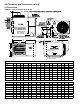
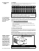
Separated Combustion Models - Whether using the suspension points or a hanger
kit, when installing a Separated Combustion Model, any unused suspension points
on the control side of the heater MUST be plugged. Plug these holes with the 1/2”
long cap screws and at washers shipped in the bag with the heater. (See FIGURE 6.)
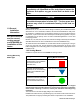
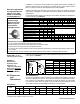
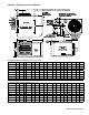
5.1 Weights
Before suspending the heater, check the supporting structure to be used to verify that
it has sufcient load-carrying capacity to support the weight of the unit.
Standard Power Vent Model
Size 30 45 60 75 100 125 150 175, 200 225 250 300 350 400
lbs 54 59 67 72 96 101 172 187 203 215 269 294 306
kg 24 27 30 33 44 46 78 85 92 98 122 133 139
Separated Combustion Model
Size 30 45 60 75 100 125 150 175, 200 225 250 300 350 400
lbs 55 60 68 73 97 102 173 188 204 216 270 295 307
kg 25 27 31 33 44 46 78 85 93 98 122 134 138
FIGURE 6 - Separated
Combustion Models
- Plug the unused
suspension points on
the control side of the
heater with the three
1/2” long screws, P/N
203311, and the three
sealing washers, P/N
61658. Find the screws
and washers in the
literature bag shipped
inside the heater.
WARNING
Unit must be level for proper operation. Do not place or add additional
weight to the suspended heater. Hazard Levels, page 2
.
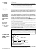
In some cases, the heat exchanger tubes could shift during shipment, causing vibration
noise against the support during unit operation. The primary function of the heat
exchanger tube support is to support the heat exchanger tubes during shipment. This
support can be removed without affecting the operation of the unit. It is recommended
that the support be removed prior to installing the unit.
Listed below is the steps needed to remove this support:
• Remove the discharge air louvers. Be careful not to lose the springs.
• Remove and discard the two screws located on top of the unit that secure the
heat exchanger support.
• Remove the heat exchanger support through the discharge opening and discard
the support.
• Reinstall the discharge air louvers.
5.1.1 Field-Removal
of Heat Exchanger
Tube Support - Model
Sizes 30 thru 125
(Optional)