Document No D300519 (03-17) Obsoletes Document No D300519 (04-08-15) Installation / Operation Applies to: Standard Power Vent Unit Heaters: Separated Combustion Unit Heaters: NOTE: Accessories referenced in this installation manual may not apply to all models.
Table of Contents 1. General........................................................ 2-4 7. Electrical Supply and Wiring................. 16-22 1.1 Hazard Labels and Notices............................. 2 1.2 General Installation Information..................... 3 1.3 Warranty........................................................... 4 1.4 Installation Codes............................................ 4 7.1 General........................................................... 16 7.2 Supply Wiring.........
WARNING Do not use this appliance if any part has been under water. Immediately call a qualified service technician to inspect the appliance and replace any gas control that has been under water. CAUTION Unit heaters should not be installed in an environment where the ambient temperature is below 50°F. The low space temperature may result in condensate forming in the heat exchanger. 1.
1.0 General (cont’d) 1.3 Warranty Refer to the limited warranty information on the Warranty Card in the “Literature Bag”. Warranty is void if ... a. Wiring is not in accordance with the diagram furnished with the heater. b. The unit is installed without proper clearance to combustible materials. c. A fan model is connected to a duct system or if the air delivery system is modified. 1.4 Installation Codes These units must be installed in accordance with local building codes.
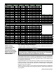
Dimensions X, Y, and Z (feet) Models with Standard Horizontal Louvers at Mounting Heights of 5 - 18 ft Y Z X Y Z X Y Z X Y Z 5 ft 6 14 30 -21° 7 16 40 -20° 8 18 45 -16° 9 20 57 -14° 9 20 59 -18° 10 22 65 -14° 8 ft 7 13 26 -39° 9 16 37 -34° 10 18 42 -29° 12 22 54 -25° 11 21 56 -28° 12 23 63 -24° 10 ft 6 11 22 -52° 9 15 33 -43° 10 17 39 -37° 12 22 52 -32° 12 20 52 -36° 13 24 60 -30° 12 ft - - - - 8 12 27 -55° 10 16 3
2.0 Unit Heater Location (cont’d) 2.2 Location Recommendations (cont’d) When units are located in the center of the space to be heated, the air should be discharged toward the exposed walls. In large areas, units should be located to discharge air along exposed walls with extra units provided to discharge air in toward the center of the area.
In addition, if the heater is being installed at an altitude above 6000 ft (1830M), the pressure switch will have to be changed. If ordered with the unit as Option DJ20 or DJ21, the pressure switch is shipped separately for field installation. Gas valve adjustment for high altitude can only be done after heater is operating; see Paragraph 6.1.
4.0 Clearances and Dimensions (cont’d) 4.
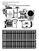
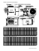
FIGURE 5 - Separated Combustion Models Separated Combustion Model Dimensions (inches ± 1/16) Size A B C D E F G H J 30, 45 12-1/8 26-5/8 10 13-13/16 26 21-9/16 5-3/16 6-1/2 60 15-1/8 26-5/8 13 13-13/16 27 21-9/16 7-7/8 6-1/2 5-1/2 75 15-1/8 26-5/8 13 13-13/16 27-5/8 21-9/16 7-7/8 6-1/2 5-1/2 100 23-1/8 26-5/8 21 13-13/16 28-5/8 21-9/16 14-1/2 6-1/2 125 23-1/8 26-5/8 21 13-13/16 29-3/8 21-9/16 14-1/2 150, 175, 200 20-1/8 38-3/16 16 23 42 35-3/8 225, 250 26-1/8 38-3/1
5.0 Hanging the Heater 5.1 Weights Before suspending the heater, check the supporting structure to be used to verify that it has sufficient load-carrying capacity to support the weight of the unit.
5.2.1 Two-Point or Four-Point Suspension The heater is equipped for either two-point or four-point suspension. A 3/8”-16 threaded nut retainer is located at each suspension point. NOTE: Four-point suspension is required when installing an optional downturn nozzle. See Dimensions in Paragraph 4.2 and the illustration in FIGURE 7A.
6.0 Mechanical (cont’d) 6.1 Gas Piping and Pressures (cont’d) 6.1.1 Gas Supply and Connections (cont’d) Sizing Gas Supply Line Capacity of Piping Cubic Feet per Hour based on 0.3" w.c. Pressure Drop Specific Gravity for Natural Gas -- 0.6 (Natural Gas -- 1000 BTU/Cubic Ft) Specific Gravity for Propane Gas -- 1.
FIGURE 9 - Gas connection is at the pipe nipple that extends outside the cabinet. Illustration shows both a vertical and horizontal gas supply; requirements are the same. Measuring valve outlet gas pressure cannot be done until the heater is in operation.
6.0 Mechanical (cont’d) 6.1 Gas Piping and Pressures (cont’d) 6.1.2 Valve Outlet or Orifice Pressure Setting (cont’d) 6.1.3 Derate by Valve Outlet Pressure Adjustment for High Altitude Operation This adjustment can only be done after the heater is in operation. High altitude adjustment is included in the startup Steps. NOTE: If elevation is above 6000 ft (1830M), a high altitude pressure switch is required; see Paragraph 3.2.1.
5. With the heater operating determine that the inlet pressure to the heater for natural gas is between 5 and 13.5 inches w.c. and for propane between 11 and 13.5 inches w.c. Take this reading as close as possible to the heater (Heaters are equipped with gas valves that have an inlet pressure tap.) If the inlet pressure is not within the specified range, the inlet pressure must be corrected and Steps 3 and 4 repeated. 6.
6.0 Mechanical (cont’d) (Note: For Separated Combustion Model, see Venting Manual for combustion air requirements.) Combustion Air Requirements for a Heater Located in a Confined Space applies to Standard Power Vent Models and Standard Power Vent Models with CV Option FIGURE 11 - Definition of Confined Space and Required Openings for Combustion Air 7.0 Electrical Supply and Wiring CAUTION: Route wires so that they do not contact the flue wrapper or venter housing. Page 16, D300519 PN 195673 R30 6.
7.2 Supply Wiring Check the rating plate on the heater for the supply voltage and current requirements. A dedicated line voltage supply with disconnect switch should be run directly from the main electrical panel to the heater. All external wiring must be within approved conduit and have a minimum temperature rise rating of 60°C. Conduit must be run so as not to interfere with the heater access panel.
7.0 Electrical Supply and Wiring (cont’d) 7.
FIGURE 14B - Typical Wiring Diagram for all Two Stage Gas Valve Models (NOTE: Two Stage Valve circuit - NOT available on all models) ALL TWO STAGE GAS VALVE MODELS D300519 PN 195673 R30,Page 19
7.0 Electrical Supply and Wiring (cont’d) 7.5.1 Combustion Air Proving (Pressure) Switch The combustion air proving switch is a pressure sensitive switch that monitors air pressure to ensure that proper combustion airflow is available. On Standard Power Ventmodels, the switch is a single pole/normally open device which closes when a negative pressure is sensed in the venter housing.
Sizes 30-125 are equipped with a temperature activated manually reset flame rollout switch. The flame rollout switch is located at the top of the burner assembly. It is factory set and is non-adjustable. If the setpoint is reached, the flame rollout acts to interrupt the electric supply to the gas valve. If the flame rollout switch activates, identify and correct the cause before resetting the switch. Refer to the Maintenance Section, Paragraph 10.2.
8.0 Controls and Operation (cont’d) 8.2 DDC Controls, Options D10 and D14 (ONLY for sizes 150-400) If the heater was ordered with Option D10 or D14, it is equipped with a Novar Minio control module. The Novar control with its accompanying relays and power transformer are mounted in the control compartment of the unit. See FIGURE 15A. This control offers a wide variety of input and output points that can be configured to meet a wide range of building management applications.
8.3 Ignition System This heater is equipped with a direct spark integrated control module (circuit board). The module monitors the safety devices and controls the operation of the fan and venter motors and the gas valve between heat cycles. FIGURE 16 – DSI Integrated Control Module (circuit board) LED lights are visible through a viewport on Separated Combustion Models. Remove door panel to view LED lights on Standard Power Vent Models.
8.0 Controls and Operation (cont’d) Normal Heat Cycle Operating Sequence (cont’d) 8.3 Ignition System (cont’d) 7) Fan/Blower Off Delay - The fan/blower motor is de-energized after a fan/blower off delay (120 seconds). Timing begins when the thermostat is satisfied. Abnormal Heat Cycle Functions Interrupted Thermostat Call for Heat - If the thermostat demand for heat is removed before the flame is recognized, the control will run the venter motor for the post purge period and de-energize all outputs.
If a call for heat (W) occurs during continuous fan, the fan/blower will de-energize. A call for fan is ignored while in lockout. Continuous Fan Operation Fault Modes Undesired Flame - If flame is sensed longer than 20 seconds while the gas valve is de-energized, the control shall energize the venter motor and fan/blower motor on heat speed. When flame is no longer sensed, the venter motor will run through postpurge, and the fan/blower motor will run through the selected heat fan off delay time.
9.0 Commissioning and Startup 9.1 Check the installation prior to startup: Check to be sure that all screws used to hold shipping brackets were reinstalled in the heater cabinet. Check suspension. Unit must be secure and level. Check clearances from combustibles. Requirements are in Paragraph 4.1. Check vent system to be sure that it is installed according to the instructions in the appropriate Vent Installation Manual as listed in Paragraph 2.2.
Operating Sequence FIGURE 17 - Gas Valve Top View ON/OFF Switch 1. Set thermostat at lowest setting. 2. Turn off all electric power to the appliance. 3. This appliance is equipped with an ignition device which automatically lights the burner. Do not try to light the burner by hand. Open the access door and locate the gas control (ON/OFF) knob or switch on the gas valve. (See FIGURE 17.) 4.
9.0 Commissioning and Startup (cont’d) With the unit in operation, measure valve outlet gas pressure. If operated at high 9.3 Check installation after startup (cont’d) Turn the unit off and on, pausing two minutes between each cycle. Observe for smooth ignition. altitude, adjust outlet gas pressure for altitude. See information and instructions in Paragraph 6.1.
10.1 Maintenance Schedule Maintenance Schedule - The following procedures should be carried out at least annually (See FIGURE 18 and Paragraphs 10.2.1 - 10.2.14.): • Clean all dirt, lint, and grease from the combustion air opening (Standard Power Vent) and venter assembly. • Clean all dirt, lint, and grease from the fan blade, fan guard, and motor. • Check the heat exchanger both internally and externally. • Check the burner for scale, dust, or lint accumulation. Clean if needed.
10.2 Maintenance Procedures 10.2.1 Heat Exchanger Maintenance Remove any external dirt or dust accumulation. Visually check the heat exchanger for cracks and holes. If a crack or hole is observed, replace the heat exchanger. NOTE: Inspection of the lower portion of the heat exchanger is done with the burner removed. See the Burner Service section below for information on inspecting the lower portion of the heat exchanger. 10.2.
Inspect and Clean the Burner With the burner assembly removed, shine a flashlight on the burner ribbons. Look for carbon buildup, scale, dust, lint, and/or anything that might restrict flow through the spaces between the burner ribbons. Holding the burner assembly so that any foreign material will fall away from the burner, use a stiff bristle brush to loosen and remove any foreign material(s). If the burner is excessively dirty, remove one of the burner end caps.
10.0 Maintenance and Service (cont’d) 10.2 Maintenance Procedures (cont’d) 10.2.4 Ignition System (cont’d) Do not attempt to disassemble the control module. However, each heating season check the lead wires for insulation deterioration and good connections. Proper operation of the direct spark ignition system requires a minimum flame signal of 1.0 microamps as measured by a microampmeter. For further information and check out procedure on the direct spark ignition system, refer to Paragraph 8.
5. Reconnect the fan motor wires according to the wiring diagram and close the access panel. 6. Restore power to the heater and turn on the gas. Light, following the instructions on the lighting instruction plate. Check for proper operation. 10.2.6 Venter Motor and Wheel FIGURE 23 - Venter Wheel Position on Shaft Replacement Instructions Remove dirt and grease from the motor casing, the venter housing, and the venter wheel. Venter motor bearings are permanently lubricated.
10.0 Maintenance and Service (cont’d) 10.2 Maintenance Procedures (cont’d) FIGURE 24 - Pressure Tap for Checking Gas Flow Shutoff 10.2.7 Operating Gas Valve (cont’d) Single-Stage Valves 1/8” Outlet Pressure Tap 1/8” Outlet Pressure Tap Two -Stage Valve 1/8” Outlet Pressure Tap NOTE: Operational pressure settings and instructions for checking pressure settings are in Paragraph 6.1.
See FIGURE 18, page 30, for location. Use a voltmeter to verify that there are 24 volts output from the transformer. If the transformer is not functioning, it must be replaced. Use a replacement transformer identical to the factory-installed model. 10.2.12 Transformer 10.2.13 Disconnect Switch - Separated Combustion model only 10.2.14 Vent or Vent/ Combustion Air System 10.
10.3 Troubleshooting (cont’d) General Troubleshooting PROBLEM PROBABLE CAUSE REMEDY Venter motor will not start 1. No power to unit. 1. Turn on power, check supply fuses or circuit breaker. 2. No 24 volt power to integrated circuit board. 2. Turn up thermostat; check control transformer output. 3. Integrated circuit board fuse blown. 3. Correct cause. Replace fuse (type ATC or ATO, 32VDC, 3A). 4. No power to venter motor. 4. Tighten connections at circuit board and/or motor terminals. 5.
No heat (Heater Operating) Fan or venter motor will not run 1. Incorrect valve outlet pressure or orifice. 1. Check valve outlet pressure. See Rating plate for manifold pressure. 2. Cycling on limit control. 2. Check air throughput. 3. Improper thermostat location or adjustment. 3. See thermostat manufacturer's instructions. 1. Circuit open. 1. Check wiring and connections. 2. Defective integrated circuit board. 2. Replace board. 3. Defective motor or starter. 3. Replace motor or starter.
APPENDIX TECHNICAL DATA - Sizes 30 - 125 (Data applies to all Models unless noted otherwise.) Size Input Heating Capacity 30 45 60 75 BTUH 30,000 45,000 60,000 75,000 kw 8.8 13.2 17.6 22.0 30.8 82 83 83 83 83 83 BTUH 24,600 37,350 49,800 62,250 87,150 99,600 Thermal Efficiency (%) Output Heating Capacity A 100 125 105,000 120,000 35.2 kw 7.2 11.0 14.6 18.3 25.6 29.
INDEX A Abnormal Heat Cycle Functions 24 Aircraft Hangars 4 Control Amps 38 Full Load Amps 38 APPENDIX 38 B Clean the Burner 31 Burner Maintenance 30 Burner Orifice 31 Burner Removal 30 C California Warning Label 4 Ceiling Suspension Kit 11 Certification 3 Check installation after startup 27 Check the installation prior to startup 26 Check the Lights 35 Chlorine 6 Clearances 7 LED Codes 23, 35 Combustion Air 16 Combustion Air Inlet 38 Combustion Air Pressure Switch 34 Combustion Air Proving (Pressure)S
INSTALLATION RECORD - to be completed by the installer: Installer: Name ________________________________________________________ Company ________________________________________________________ Address ________________________________________________________ ________________________________________________________ ________________________________________________________ Phone _________________________________ Distributor (company from which the unit was purchased): Company _______________