
UDAP Installation Manual


Page 20, D300519 PN 195673 R30
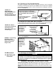
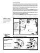
7.5.1 Combustion Air Proving (Pressure) Switch
The combustion air proving switch is a pressure sensitive switch that monitors air pressure
to ensure that proper combustion airow is available. On Standard Power Ventmodels,
the switch is a single pole/normally open device which closes when a negative pressure
is sensed in the venter housing. On Separated Combustion models, the switch senses
the differential pressure between the negative pressure in the venter housing and the
pressure in the cabinet. (For switch location, see FIGURE 18, page 30.)
On startup when the heater is cold, the sensing pressure is at the most negative level,
and as the heater and ue system warm up, the sensing pressure becomes less
negative. After the system has reached equilibrium (about 20 minutes), the sensing
pressure levels off.
If a restriction or excessive ue length or turns cause the sensing pressure to be
outside the switch setpoint, the pressure switch will function to shutoff the main burner.
The main burner will remain off until the system has cooled and/or the ue system
resistance is reduced.
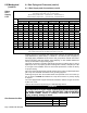
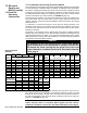
The Tables on the left below list the approximate water column negative pressure
readings and switch setpoints for sea level operating conditions for Standard Power
Vent and Model heaters. The Table on the right lists the approximate water column
differential pressure readings and switch setpoints for sea level operating conditions
for Separated Combustion Model heaters.
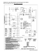
7.5 Electrical
Operating
Components
Pressure Switch
Settings
DANGER
Safe operation of this unit requires proper venting ow. NEVER
bypass combustion air proving switch or attempt to operate the
unit without the venter running and the proper ow in the vent
system. Hazardous conditions could result. See Hazard Intensity
Levels, page 2.
Std Power
Vent
Models
Startup
Cold
Equilibrium
Hot
Setpoint OFF
Setpoint
ON
Label
Color
Switch
P/N
Std Power
Vent
Models
Startup
Cold
Equilibrium
Hot
Setpoint
OFF
Setpoint
ON
Label
Color
Switch
P/N
Negative Pressure (" w.c.) Differential Pressure (" w.c.)
30 1.0 0.8 0.4 0.6 Green 197030 30 1.0 0.8 0.65 0.8 Yellow 197028
45 1.0 0.8 0.4 0.6 Green 197030 45 1.1 0.8 0.65 0.8 Yellow 197028
60 1.0 0.8 0.5 0.7 Orange 196388 60 1.1 0.9 0.65 0.8 Yellow 197028
75 1.0 0.9 0.5 0.7 Orange 196388 75 1.1 0.9 0.65 0.8 Yellow 197028
100 0.9 0.7 0.5 0.7 Orange 196388 100 0.9 0.7 0.55 0.7 White 196362
125 0.8 0.6 0.4 0.6 Green 197030 125 0.8 0.6 0.45 0.6 Pink 197032
150, 175 0.8 0.7 0.4 0.6 Green 197030 150, 175 0.8 0.6 0.40 0.6 Green 197030
200, 225 2.2 1.5 1.1 1.3 Blue 201158 200, 225 2.2 1.5 1.10 1.3 Blue 201158
250, 300 2.3 1.6 1.1 1.3 Blue 201158 250, 300 2.3 1.6 1.10 1.3 Blue 201158
350, 400 2.6 1.8 1.1 1.6 Red 201159 350, 400 2.6 1.8 1.10 1.6 Blue 201158
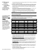
Std Power Vent
Model with Opt AV6
Startup Cold
Equilibrium
Hot
Setpoint
OFF
Setpoint
ON
Label
Color
Switch
P/N
Negative Pressure (" w.c.)
30 1.1 0.8 0.65 0.8 Yellow 197028
45 1.1 0.8 0.50 0.7 Orange 196388
60 0.9 0.8 0.60 0.8 Lt Blue 197029
75 1.0 0.8 0.60 0.8 Lt Blue 197029
100 0.9 0.7 0.55 0.7 White 196362
7.5.2 Limit Control
All units are equipped with a temperature activated auto reset limit control. The con-
trol is factory set and is non-adjustable. If the setpoint is reached, the limit control will
interrupt the electric supply to the gas valve. This safety device provides protection in
the case of motor failure or lack of airow due to a restriction at the inlet or outlet. (For
location, see FIGURE 18, page 30.)
CAUTION: The auto reset limit control will continue to shut down the
heater until the cause is corrected. Never bypass the limit control;
hazardous conditions could result. See Hazard Intensity Levels, page 2.
7.0 Electrical
Supply and
Wiring (cont’d)