
Replacement Limit Controls
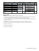


Form P-FAN&LIMIT, Page 6
Fan Control
Limit Control
Location of Original Equipment Fan
Control - Sizes 30-105
SECTION 2B -
Installing
Replacement Fan
Control on Models
(C)XL, (C)EEXL,
(C)XLB, and
(C)EEXLB
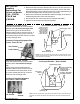
Instructions for Sizes 30-105
Locate the replacement fan control bracket
assembly at the rst heat exchanger tube.
Position to the right of the tube seam as
illustrated. Attach with the screws in the kit. It
is important that the spring action of the fan
control bracket allow the fan control to contact
the heat exchanger tube.
Fan Control Position - Sizes 30-105
1. Turn off the gas and the electric.
2. Disconnect and remove the defective fan control. If the fan control is on
a spring-loaded bracket as illustrated in the photos, remove the entire
bracket assembly. Earlier models have the fan control seated directly on
the heat exchanger base; remove the fan control only.
3. Refer to the instructions and illustration below that apply to the Size of
heater being serviced. Follow the instructions.
4. Re-connect the fan control wires and re-assemble the heater.
5. Light the heater and check for proper operation.
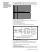
Fan Control Position - Sizes 125-400
NOTE: If the fan control that was removed did not include a bracket; use the
left hole and drill a #20 hole to attach the bracket. Be certain the fan control
will be positioned as illustrated.
Instructions for Sizes 125-400
Locate the replacement fan control bracket
assembly at the second heat exchanger
tube.
Position to the left of the tube seam as
illustrated. Attach with the screws in the kit.
It is important that the spring action of the
fan control bracket allow the fan control to
contact the heat exchanger tube.
Limit
Control
Fan Control
Location of Original Equipment
Fan Control - Sizes 125-400
NOTE: If the fan control that was removed did not include a bracket; use the left hole and
drill a #20 hole to attach the bracket. Be certain the fan control will be positioned as illus-
trated.