
User Manual

7
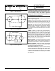
MaximumOver-currentProtection(MOP)information,
refer to the unit rating label. For proper high voltage
wiring or other wiring requirements refer to the Wiring
Diagram (Figure 7).
• Internally mounted circuit breakers are available as
field installed options. These circuit breakers can be
used as an electrical disconnect.
Thermostat Connections
• Thermostatconnectionsshallbeinaccordancewiththe
instructions supplied with the thermostat and the indoor
equipment. The low voltage wires must be properly
connected to the units low voltage terminal block.
• Asinglestagethermostatisusedwiththisequipment
and must operate in conjunction with any installed
accessories. A typical AC and air handler hookup is
shown in Figure 9 (page 18). For heat pump and air
handler connections, see Figure 10 (page 19).
• Thethermostatshouldbemountedabout5feetabove
theooronaninsidewall.DONOTinstallthethermostat
on an outside wall or any other location where its
operation may be adversely affected by radiant heat from
fireplaces, sunlight, or lighting fixtures, and convective
heat from warm air registers or electrical appliances.
Refer to the thermostat manufacturer’s instruction sheet
for detailed mounting and installation information.
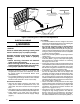
Electrical Wiring with a Duct Heater
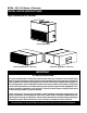
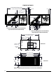
Slip-in duct heaters are available as an accessory with
the B5SM air handler. See Table 2 for available sizes.
These heaters mount in the supply duct external to the
air handler. The heater kits are available in 10, 16, 26,
and 36 KW sizes and 240 or 460 voltages. All heater kits
are set up for three phase operation. To wire the heater
kits to the B5SM air handler unit, refer to the Installation
Instructions supplied with the kit.
SKU Kw Volts/Phase/Hz MODEL
559428 10 208-240/3/60 H7HK010Q-01
559429 10 480/3/60 H7HK010S-01
559430 16 208-240/3/60 H7HK016Q-01
559431 16 480/3/60 H7HK016S-01
559432 26 208-240/3/60 H7HK026Q-01
559433 26 480/3/60 H7HK026S-01
559434 36 208-240/3/60 H7HK036Q-01
559435 36 480/3/60 H7HK036S-01
Table 2. Duct Mount Heater Kit Models
Example
:
AB = 451V
BC = 460V
AC = 453V
2. Determine the average voltage in the power supply.
3. Determine the maximum deviation:
4. Determine percent of
voltage imbalance by
using the results from
steps 2 & 3 in the following
equation.
maxvoltage deviation
fromaverage voltage
=100 x
averagevoltage
% Voltage Imbalance
6
454
100
x
= 1.32%
Example:
1. Measure the line
voltages of your 3-phase
power supply where it
enters the building and
at a location that will
only be dedicated to the
unit installation. (at the
units circuit protection or
disconnect).
Unbalanced 3-Phase Supply Voltage
Voltage unbalance occurs when the voltages of all phases
of a 3-phase power supply are no longer equal. This
unbalance reduces motor efficiency and performance.
Some underlying causes of voltage unbalance may include:
Lack of symmetry in transmission lines, large single-phase
loads, and unbalanced or overloaded transformers. A
motor should never be operated when a phase imbalance
in supply is greater than 2%.
Perform the following steps to determine the percentage
of voltage imbalance:
In this example, the measured line voltages were
451, 460, and 453. The average would be 454 volts
(451 + 460 + 453 = 1,364 / 3 = 454).
Example:
From the values given in step 1, the BC voltage
(460V) is the greatest difference in value from
the average:
460 - 454 = 6
454 - 451 = 3
454 - 453 = 1
Highest Value
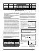
Table 1. Electrical Rating Data
Model Phase Hertz Voltage
Blower Motor
MCA MOP
Unit
Configuration
Hp FLA SFA
-090Ja 3 60 208-230/460
1 3.2-3.0/1.5 3.5-3.3/1.7 4.4-4.2/2.2 15 Factory Std.
1.5 4.4-4.2/2.1 5.0-4.6/2.3 6.3-5.8/2.9 15 w/ MSD kit
-120Ja 3 60 208-230/460
1.5 4.4-4.2/2.1 5.0-4.6/2.3 6.3-5.8/2.9 15 Factory Std.
2 6.0-5.8/2.9 6.7-6.4/3.2 8.4-8.0/4.0 15 w/ MSD kit
-090Ka & -120Ka 1 60 208-230 2 11.3 - 10.0 11.3 - 11.0 14.2 - 13.8 25 - 20 Factory Std.
FLA=FullLoadAmps,MCA=MinimumCircuitAmpacity,MOP=MaximumOver-CurrentProtection