
User Manual

6
ELECTRICAL WIRING
WARNING:
ELECTRICAL SHOCK, FIRE OR EXPLOSION
HAZARD
Failure to follow safety warnings exactly could
result in serious injury or property damage.
Improper servicing could result in dangerous
operation, serious injury, death or property
damage.
• Before servicing, disconnect all electrical
power to the indoor blower.
• Whenservicingcontrols,labelallwiresprior
to disconnecting. Reconnect wires correctly.
• Verifyproperoperationafterservicing.
• Electrical connections must be in compliance with
all applicable local codes and ordinances, and with
the current revision of the National Electric Code
(ANSI/NFPA 70).
• ForCanadianinstallations,theelectricalconnections
and grounding shall comply with the current Canadian
Electrical Code (CSA C22.1 and/or local codes).
Pre-Electrical Checklist:
√ Verify that the voltage, frequency, and phase of the
supply source match the specifications on the unit
rating plate. The label is located near the refrigerant
lines.
√ Verify that the service provided by the utility is sufficient
to handle the additional load imposed by this equipment.
√ Phase balance on 3 phase units must always be
checked. See Unbalanced 3-Phase Supply Voltage
(page 7).
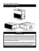
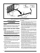
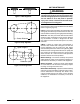
Figure 1. Converting from 1” Filter to 2” Filter Applications
BRACKET CONFIGURATION FOR
2” FILTER APPLICATIONS
BRACKET CONFIGURATION
FOR 1” FILTER APPLICATIONS
(FACTORY SETTING)
“Z” BRACKET
“L” BRACKET
REMOVE 4 SCREWS FROM
FILTER RACK FRAME
FILTERS
FILTER BRACKET
LOCATION
REMOVE 4 SCREWS SECURING
“Z” BRACKET AND “L” BRACKET
Line Voltage
• Itisrecommendedthatthelinevoltagetotheunitbe
supplied from a dedicated branch circuit containing the
correct fuse or circuit breaker for the unit.
• An electrical disconnect must be located within
sight of and readily accessible to the unit. This
switch shall be capable of electrically de-energizing the
outdoor unit. See unit data label for proper incoming field
wiring. Any other wiring methods must be acceptable
to authority having jurisdiction.
• Refertotheunitwiringlabelforproperhighandlow
voltage wiring.
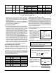
• Useonlycopperwireforthelinevoltagepowersupply
to this unit (Table 1, page 7). Use proper code agency
listed conduit and a conduit connector for connecting
the supply wires to the unit.
• Overcurrentprotectionmustbeprovidedatthebranch
circuit distribution panel and sized as shown on the unit
rating label and according to applicable local codes.
See the unit rating plate for maximum circuit ampacity
and maximum overcurrent protection limits.
• If replacing any of the original wires supplied with
the unit, the replacement wire must be copper wire
consisting of the same gauge and temperature rating.
• Providepowersupplyfortheunitinaccordancewith
the unit wiring diagram, and the unit rating plate. The
installer should become familiar with the wiring diagram/
schematic before making any electrical connections to
the unit. See Figure 7 (page 17).
• Theseairhandlerscanbepurchasedinbothsingle
and three phase power configurations, all single phase
equipment is shipped from the factory ready for field
connections. For electrical connection locations see
Figures 4 or 5 (pages 10 or 11).
• Threephaseunitsareshippedfromthefactorypre-
configured for high voltage operation. The 460 volt,
60 hertz units may be reconfigured in the field for
the other voltages indicated on the unit rating label .
For additional Maximum Current Ampacity (MCA), or