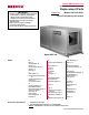
Form P-ADF (Version C.1) Obsoletes Form P-ADF (Version C) Replacement Parts IMPORTANT Applies to: Models ADF and ADFH, Direct-Fired Makeup Air Heaters 1. Always include complete heater model and serial number so that any specification change can be considered for parts shipment. It can save time and expense. 2. Specifications are subject to change without notice. 3. We reserve the right to substitute functional replacements. 4. Order either by Kit or Component Part No.
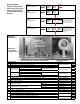
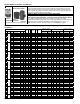
Rating Plate and Serial No. Rating Plate Codes: Sample of a Rating Plate REZNOR MERCER, PA. USA 16137 ® ANSI Z83.4/CSA 3.7-2013 NON-RECIRCULATING DIRECT-FIRED INDUSTRIAL AIR HEATER ANSI Z83.4/CSA 3.
Model ADF/ADFH System Configurations (Sizes 300 and 500 have a single blower; Sizes 700 and 1200 have dual blowers.
CODE Description 13 Bushing and Insect Screen for Sensing Probes (not illustrated) 14 Convenience Outlet Receptacle, Hubbell #GF5352-1 15 Dirty Filter Pressure Switch, Tri-Delta #AP4434, set at .3" w.c.
Code 25 - Thermostats (Wall mounted Option CL; or mounted on the console, Opt RCT, below) 1-Stg Heat/Cool, 24v snap acting thermostat (50-90°F) w/fan auto-on & cool-off-heat switches 2-Stg Heat/Cool, 24v digital thermostat (40-90°F) with fan auto-on function P/N 255350 (same as CL1 & RCT1) 1-Stg Heat/Cool, 24v programmable thermostat (45-88°F) with fan autoon and cool/off/heat. P/N 220630 (same as CL22 & RCT2) P/N 220632 (same as CL52) Code 26 Thermostat Guards P/N 257464, 6x5x2.
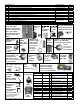
Blower Motors, Contactor, and Starters CODES 47A&B and 50 Starter (Option AN10) CODE 46 CODE 45 - Blower Motor Motors in the table below that do not have a CODE 46 contactor listed do not have internal overload protection and MUST be used with the CODE 47 motor starter and starter overload. If a CODE 46 contactor is listed, motor may be used with either the contactor or an optional starter and overload.
CODE 45 - Motor Type hp Open Shaft volt ph fla Service Power Factor Factor EFF. CODE 47A - Starter Contactor w/24 volt coil CODE 47B - Starter Overload CODE 46 - Motor Contactor (Option AN2) P/N Mfr No. Frame Mfr No. P/N min max GE # P/N Mfr No. P/N 105855 AO-E300 213T 19.4 1-3/8" 240 3 CL25A310T-1 151278 17.5 22.0 RTA1-T 151197 ============ ====== 105855 AO-E300 213T 9.7 1-3/8" 480 3 CL00A310T-1 151275 8.0 12.
CODE 45 - Motor Type hp Service Power Factor Factor Shaft volt ph CODE 47A - Starter Contactor w/24 volt coil EFF. CODE 47B - Starter Overload CODE 46 - Motor Contactor (Option AN2) P/N Mfr No. Frame fla Mfr No. P/N min max GE # P/N Mfr No. P/N 105846 AO-K313 215T 39 1-3/8" 240 1 CL06A311M-1 203687 30.0 43.0 RTA2-E 151206 ============ ====== 158173 AO-E357 215T 30 1-3/8" 208 3 CL04A310M-1 151279 25.0 32.
Blower Motor Starters with Line Volt Coil - used before 9/03 (Serial No. Date Code BCI)) CODE 50 - Starter Contactor with line voltage coil and Overloads (used on units mfgd prior to 9/03) volt ph Mfg No. P/N min max GE # P/N 120 1 CL00A310T-J 151146 8.00 12.00 RTA1-N 151193 208 1 CL00A310T-L 151150 4.00 6.30 RTA1-L 151191 240 1 CL00A310T-S 151147 4.00 6.30 RTA1-L 151191 208 3 CL00A310T-L 151150 1.90 2.70 RTA1-J 151189 240 3 CL00A310T-S 151147 2.50 4.10 RTA1-K 151190 480 3 CL00A310T-U 151148 1.30 1.
Motor Contactor, and Starters (cont'd) Voltage GE # Reznor® P/N 24 120 208 230 460 575 LB1A-C LB1A-J LB1A-L LB1A-S LB1A-U LB1A-Y 151280 151281 151282 151283 151284 151285 CODE 51 - Replacement Coils by Voltage for IEC Starter Contactors (CODE 46 - 24 volt starter contactors on pages 6-8 and CODE 50 line voltage starter contactors on page 9) For Use with Contactors Beginning with GE# CL00; CL01; CL02; CL25 Voltage GE # Reznor® P/N 24 120 208 230 460 575 LB3A-C LB3A-J LB3A-L LB3A-S LB3A-U LB3A-Y
CODE 64 - Temperature Selectors (see chart for option application) P/N 86988, TD114 U.S. Models, Range 55-90°F (selector with box, P/N 156085); P/N 101165, TD114, Canadian Models, Range 50-75°F; P/N 87107, TD114A, P/N 86990, Range 80-130°F; Selectrastat P/N 159285, TD114B, Maxitrol Range 120-160°F T-244 Gas Regulators, Valves, and Pressure Switches NOTE: Serial No. Date Code for 9/03 is BCI (See page 2.) P/N 70 1" Pressure Regulator, RV53-88 123950 71 Regulator, 1" manifold, 5 PSI to 6" w.c.
Gas Regulators, Valves, and Pressure Switches (cont'd) Components in Gas Control Option AG3 beginning 9/03 CODE 82 2-Stage Valve used prior to 9/03, 1/2", P/N 177396 or 3/4", P/N 177397 CODE 85 - Mechanical Modulation Valve used prior to 9/03, P/N 131455 CODE 88A Description Valve only, 1" fluid power, Honeywell #V5055A1004 86992 Gas Valve, Watts B-6000-UL-TH, with ball valve adapter 1" 1-1/4" 98 99 Pilot Gas Valve, 3/8", Jomar 7204 Vent Valve, 3/4, 24V, N.O.
CODE 98 Gas Control Regulators P/N 123916, 3/4", Maxitrol M611R P/N 87001, 1", Maxitrol M611 R-88 P/N 89351, 1-1/4", Maxitrol MR212D CODE 99 - Gas Regulator Kit, outlet pressure range 1 - 12" (maximum 5 psi) P/N 91071, 2", Maxitrol MR212E P/N 124258 (Same as Option CZ1), Kit includes Maxitrol 1"x1" NPT regulator P/N 124259 (Same as Option CZ2), Kit includes Maxitrol 1-1/2"x1-1/2" NPT regulator Ignition System - Hot Surface Ignition CODE 100 Descriptions Hot Surface Ignition Module, Synetek IH11040B-C,
Replacement Burners or units manufactured prior to 9/03 (cont'd) Burner End Plate showing Hot Surface Ignitor Burner Components - applies to all sizes of Maxon burners and ADF/ADFH Units CODE Description P/N 107A Burner Mixing Plate only, 6" 116104, straight section replacement Maxon P/N plate. Refer to Operation/ 20580, Maintenance/Service (qty of 6" Form, O-ADF/RDF, Burner sections Cleaning, for instructions on depends on how to access the burner length) for servicing.
CODE Description Adapter Back Assembly Adapter Back Top Adapter Back Bottom Adapter Back Center Section Adapter Back Left End Adapater Back Right End Adapter Back Left Rear Sctn Adapter Back Right Rear Sctn Vertical Blower Support - Left Vertical Blower Support - Right Standard BLOWER, Class I (Option A1) Horizontal Discharge 130 130A 130B 130C 130D 130E 130F 130G 131 132 Model / Size ADFH500 ADF/ADFH700 -------122095 -122085 106299 106943 1360, A12x12AC 100658, A15x11ACD (2)112606, A12x12AC (includes wh
Drive Components Opt AMA2 AMA3 AMA4 AM1 AM2 AM3 AM4 AM5 AM6 AM7 AM8 AM9 AM10 AM11 AM12 AK1 AK2 AK3 AK5 AK6 AK7 AK8 Drives RPM Opt 251-300 AM13 301-350 AM14 351-400 AM15 401-450 AM16 451-500 AM17 501-550 AM18 551-600 AM19 601-650 AM20 651-700 AM21 701-750 AM22 751-800 AM23 801-850 AM24 851-900 AM25 901-950 AM26 951-1000 RPM 1001-1050 1051-1100 1101-1150 1151-1200 1201-1250 1251-1300 1301-1350 1351-1400 1401-1450 1451-1500 1501-1550 1551-1600 1601-1650 1651-1700 Drive NOTES: • Service factor on all drives
Open Motor HP Option Model ADFH 300 (cont'd) CODE 140 - Motor Sheave P/N Mfr No.
Drive Tables by Model and Size (cont'd) Model ADF 700 - Horizontal Discharge Open Motor HP Option 1 AL6 CODE 140 - Motor Sheave Horizontal Drive Option (See page 16.) Discharge P/N Mfr No.
Motor HP Option Model ADF 1200 with Vertical Discharge and Model ADFH 1200 CODE 140 - Motor Sheave CODE 141 - Blower Sheave P/N Mfr No. Bore P/N Mfr No.
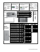
Outside Air Inlet Hood (Option AS2) Size 300 500 700 1200 170 Outside Air Hood Pkg 106202 106204 106206 Components 170A Left Side 100216 170B Right Side 100217 170C Top 100228 100230 100232 170D Bottom 100235 100237 100238 170E Louver Assembly 103774 103776 103778 CODE Description CODE 171 Outside Air Inlet Hood with Filter Cabinet Size 300 500 700 1200 w/ 1” Disposable Filters (Opt AS11) 123243 123244 123245 w/ 1” Permanent Filters (Opt AS6) 123231 123232 123233 Inside Air Inlet Hood with Filter Cabinet