
Monarco-HAT-Hardware-Reference-Manual

Monarco HAT Hardware Reference Manual 20190728-1
8
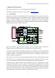
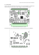
3. Hardware Description and I/O Connection Examples
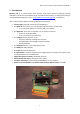
Connecting Raspberry Pi (P1) 3.1.
Interface Specification 3.1.1.
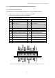
Connector type: 2×20 pin 2.54 mm pitch socket on bottom side, long pins are available on the top
board side for connection of additional devices to IOs not used by Monarco HAT
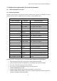
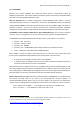
P1 – Raspberry Pi 40pin Header (pins not listed below are not used by Monarco HAT)
Pin no. on header
RPi Signal
Connection / Note
2, 4
+5V
Power supply to the RPi
3
SDA / GPIO2
I2C-1 data – RTC, 1-Wire
5
SCL / GPIO3
I2C-1 clock – RTC, 1-Wire
8
TXD0 / GPIO14
UART Tx – MCU PE11 / USART0
10
RXD0 / GPIO15
UART Rx – MCU PE10 / USART0
16
GPIO23
Optional use, MCU PB7
18
GPIO24
Optional use, MCU PB8
19
MOSI / GPIO10
SPI0 – MCU PC2 / USART2
21
MISO / GPIO9
SPI0 – MCU PC3 / USART2
23
SCLK / GPIO11
SPI0 – MCU PC4 / USART2
24
CE0# / GPIO8
SPI0 – MCU PC4 / USART2
27
ID_SD / GPIO0
I2C-0 data – ID EEPROM
28
ID_SC / GPIO1
I2C-0 clock – ID EEPROM
29
GPIO5
Optional use, MCU PA4
31
GPIO6
Optional use, MCU PA3
37
GPIO26
ID EEPROM Write Enable (low active)
38
GPIO20
MCU Bootloader Enable (high active)
40
GPIO21
MCU RESETn (low active)
6, 9, 14, 20, 25, 30, 34, 39
GND
Ground
Raspberry Pi IOs in use by Monarco HAT – do not use these as GPIOs for your applications:
SPI-0 with CE0: Primary data communication channel with Monarco MCU
UART-0: RS-485 forwarded through MCU (can be disabled) / MCU firmware update
I2C-1 (SCL, SDA): Real Time Clock, 1-Wire controller
I2C-0 (ID_SC, ID_SD): ID EEPROM according to the HAT standard
GPIO26: ID EEPROM write enable
GPIO20, GPIO21: MCU bootloader enable, MCU RESETn – Do not touch!
GPIO05, GPIO06, GPIO23, GPIO24: Optional use with MCU's GPIO (normally these signals can
be freely used, MCU keeps them floating)