
Monarco-HAT-Hardware-Reference-Manual

Monarco HAT Hardware Reference Manual 20190728-1
6
Board Layout 2.2.
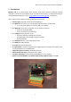
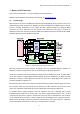
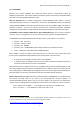
Following image shows board layout with connectors on the top side highlighted – P1 (Raspberry Pi
header), P2 (input and output signals), P3 (MCU debugger), P4 (display 5 V power output).
Image 2.2: Monarco HAT board layout – Top side.
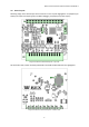
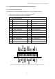
On the bottom side, location of battery holder BAT1 and LED0 to LED8 indicators are highlighted.
Image 2.3: Monarco HAT board layout – Bottom side.