
Monarco-HAT-Hardware-Reference-Manual

Monarco HAT Hardware Reference Manual 20190728-1
16
Technology Functions Overview
Digital outputs can be also driven by advanced technology functions, which are not possible with
Raspberry Pi integrated GPIOs:
PWM (Pulse Width Modulator) with frequency widely adjustable in continuous range
1 Hz to 100 kHz, which can be also considered as a versatile square-wave generator which
period and duty cycle is controlled by cyclic process data coming from Raspberry Pi,
PULSE-DIR generator for motion control based on servo drives with “pulse/dir” control
(Note: will be available in future firmware release).
Here are a few examples of devices which inputs can be driven by Monarco HAT DOUT with PWM:
solid-state-relays for power modulation of various lighting or electric heating elements,
DC motors with a proper H-bridge power stage,
small servo motors with “RC servo” type input (1 ms to 2 ms pulse width control).
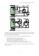
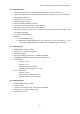
PWM Technology Function
There are two PWM hardware function modules available:
PWM1 – Output channels: A = DOUT1, B = DOUT2, C = DOUT3,
PWM2 – Output channels: A = DOUT4.
Each PWM module contains 16bit internal counter clocked by 32 MHz clock with selectable prescaler
(1, 8, 64, 512, other values possible with firmware modification) and TOP value register. Counter
value is incremented from zero up to TOP by prescaled clock. For each output channel there is a
CMPx register which represents PWM modulated value for given channel. Thanks to a synchronous
buffering on both TOP and CMPx registers, output signal is phase correct when changing both
frequency and modulated value. Prescaler selection is not buffered. It’s switched just when process
data are received so switching it during operation can lead to unexpected behavior.
Note: From the description above it’s obvious that all output channels on PWM1 module have
common output frequency.
Note: PWM2 module cannot be activated simultaneously with COUNTER2 module.
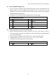
Output frequency is given by formula: f
PWM
= 32 MHz / ( prescaler · TOP )
Where prescaler can be { 1, 8, 64, 512 }, and TOP can be 0 to 65532 - it is represented by 14bit value
in process data and then multiplied by 4. Modulated value is represented by 16bits in process data
and internally scaled to 0 to TOP range. Lowest possible prescaler should be preferred for given
frequency, because it leads to bigger value of TOP and so better resolution of modulated value.
prescaler
recommended range low boundary
recommended range high boundary
1
≥ 1 kHz
TOP = 32000
≤ 100 kHz
TOP = 320
8
≥ 100 Hz
TOP = 40000
< 1 kHz
TOP = 4000
64
≥ 10 Hz
TOP = 50000
< 100 Hz
TOP = 5000
512
≥ 1 Hz
TOP = 62500
< 10 Hz
TOP = 6250