
Monarco-HAT-Hardware-Reference-Manual

Monarco HAT Hardware Reference Manual 20190728-1
10
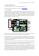
Connecting Input and Output Signals (P2), LED Indicators 3.2.
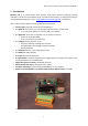
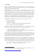
P2 Terminal Connector Pinout 3.2.1.
Connector type: 2 × 13 wire detachable terminals, push-in system by Phoenix Contact
Board side type: DMC 1,5/13-G1F-3,5-LR P20THR (1787124)
Plug side type: DFMC 1,5/13-ST-3,5-LR (1790593)
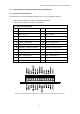
P2 – Input and Output Signals
1
GND IN – Ground / Power in 0 V
2
+24V IN – Power in +10 to +30 V
3
RS485− / RS485 B Wire
4
RS485+ / RS485 A Wire
5
GND – Ground
6
GND – Ground
7
1W DATA – 1-Wire bus Data
8
1W 5V OUT – 1-Wire bus Power
9
DOUT1 – Digital Out 1
10
DOUT2 – Digital Out 2
11
DOUT3 – Digital Out 3
12
DOUT4 – Digital Out 4
13
GND – Ground
14
+24V OUT – Power output
15
DIN COM− – Digital In. Common
16
+24V OUT – Power output
17
DIN1 – Digital Input 1
18
DIN2 – Digital Input 2
19
DIN3 – Digital Input 3
20
DIN4 – Digital Input 4
21
AIN1 – Analog Input 1
22
AIN2 – Analog Input 2
23
AGND – Analog Ground
24
+24V OUT – Power output
25
AOUT1 – Analog Output 1
26
AOUT2 – Analog Output 2
Image 3.1: P2 input-output terminal connector pinout (view from connector terminals side).