
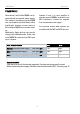
Technical data


Multi Media
Re:source
3
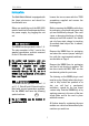
INSTALLATION
The Multi Media Module is equipped with
the latest electronics and should be
handled with care.
Before you install the card, the M51/ M10
must be switched off and separated from
the power supply, by plugging the unit
out.
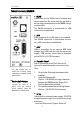
M51 Installation .
The MMM can be operated in slots 1 - 6.
The only exception is Slot 7, next to the
speaker connections, as this is reserved
for the 5.1 Decoder module.
For power load reasons, only one
MMM may be installed in an M51 if the
MMM is supplied with power
internally. If power is supplied
externally through DC IN, up to 4
MMMs can be installed at the same
time - see Page 4.
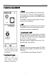
M10 Installation .
The MMM can be operated in slots 1 - 8
or A 1 - 2. Slots A1 and A2 should only be
fitted with second generation modules,
like the MMM, that have the following
symbol on them:
Up to 4 MMMs can be installed in
parallel in an M10.
Loosen the two screws with the TORX
screwdriver supplied and remove the
blanking plate.
Before removing the MMM module from
its packaging, you should make sure that
you are not statically charged. This could
cause a damaging discharge of voltage
when you touch the module. You should
get rid of any static charge by touching
an earthed metal object like a radiator,
for example.
Remove the MMM from its packaging
and select the correct jumper setting in
line with the requirements/conditions -
see the table on Page 4.
Remove the MMM from its packaging
and feed it into its plug-in position. The
two bars inside the M51/ M10 are the
mechanical guides for you to use.
The lettering on the MMM plug-in card
must be on top. Shortly before the plug-in
card is fully locked into position in its
slot, you will feel a mechanical
resistance, caused by the bus board
contact strip. Push the MMM fully in by
applying pressure in the area of the two
screw holes and fix the card in place
with both screws.
All further steps for registering the new
module are carried out automatically the
next time you switch on.
G²
!
!