
REVLC08S40A-SPAX2 Pin Lead Connection Diagram
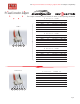

Pin Lead Connection Diagram
Pin Color Voltage Node
1 Black 0 Cell 1 Neg-
2 White 3.7 Cell 1 Pos+ / Cell 2 Neg-
3 White 7.4 Cell 2 Pos+ / Cell 3 Neg-
4 White 11.1 Cell 3 Pos+ / Cell 4 Neg-
5 Red 14.8 Cell 4 Pos+ / Cell 5 Neg-
6 Black 14.8 Cell 4 Pos+ / Cell 5 Neg-
7 White 18.5 Cell 5 Pos+ / Cell 6 Neg-
8 White 0 Unused
9 White 0 Unused
10 White 0 Unused
11 Red 22.2 Cell 6 Pos+
6 Cell Pack – CPBP7 & CPBP6P-10
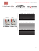
Pin Color Voltage Node
1 Black 0 Cell 1 Neg-
2 White 3.7 Cell 1 Pos+ / Cell 2 Neg-
3 White 7.4 Cell 2 Pos+ / Cell 3 Neg-
4 White 11.1 Cell 3 Pos+ / Cell 4 Neg-
5 Red 14.8 Cell 4 Pos+ / Cell 5 Neg-
6 Black 14.8 Cell 4 Pos+ / Cell 5 Neg-
7 White 18.5 Cell 5 Pos+ / Cell 6 Neg-
8 White 22.2 Cell 6 Pos+ / Cell 7 Neg-
9 White 0 Unused
10 White 0 Unused
11 Red 25.9 Cell 7 Pos+
7 Cell Pack – CPBP7 & CPBP6P-10
Page 2
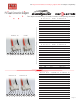
9
1011
8
7
CPBP7
3
45
2
16
CPBP6P-10
The Cellpro connectors use JST brand, PA series, 2.0mm spacing connectors
See http://www.fmadirect.com/cellpro_adapters.html for adapter compatibility.