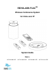
REVOLABS FLX2TM Wireless Conference System for Voice over IP System Guide Models: 10-FLX2-200-VOIP 10-FLX2-020-VOIP 10-FLX2-002-VOIP 10-FLX2-101-VOIP
© 2011 - 2012 REVOLABS, INC. All rights reserved. No part of this document may be reproduced in any form or by any means without express written permission from Revolabs, Inc. Product specifications are subject to change without notice. Revolabs FLX2 System Guide – VOIP 10-FLX2SYSGUIDEVoIP-EN March 2012 (Rev 2.0.
Introduction Congratulations on your purchase of the Revolabs FLX2TM Wireless Conference Phone. This system utilizes state of the art technology providing high band-width audio and enabling clear, reliable, un-tethered communications with your telephone, PC, mobile device, and video conferencing system. The Revolabs FLX2 Conferencing Phone allows enhanced freedom for VoIP calls and video conferences by allowing independent locations of the microphones and the speaker used during the call.
Contents Introduction ............................................................................................................................................ 3 Safety Warnings ..................................................................................................................................... 3 Contents .................................................................................................................................................... 4 General Information ...............
System Information ...................................................................................................................................... 40 Bluetooth .......................................................................................................................................................... 41 Home .................................................................................................................................................................. 41 Call............
General Information The Revolabs FLX2 Conference Phone includes several components which, in the sum, make up the conferencing phone. The components are the Charger Base, Speaker, Microphones and Dialer (handset). In addition, the Base Station receives the wireless signals from those components and connects to your VoIP network for conference calls, with your video conferencing unit to provide outstanding audio for your video calls, or to your Bluetooth enabled device such as a cell phone or computer.
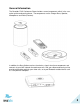
Quick setup for VoIP Conference Calls While all components delivered with the Revolabs FLX2 Conference Phone are partially charged, we recommend charging the Speaker, the Microphones, and the Dialer for at least 8 hours or overnight before starting to use the system. Connecting the Base Station Place the Base Station close to the Ethernet outlet you want to use for the conference phone. Connect the Base Station to the network using the provided Ethernet cable.
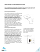
VoIP configuration For the FLX phone to work within a VoIP environment the phone has to be set up to communicate to the telephone switch. You will also have to enable the extension (user) you want to use with the FLX on your switch. Please review your switch documentation on information on how to do that. For the minimal setup, in the FLX Handset you will have to provide information on the IP connection to the telephone switch. To do this visit Setup – Advanced Setup – Network Settings – VOIP Settings.
To answer a call using the conference phone, simply remove one or more Microphones from the Charger Base when the Speaker rings. If a microphone is already out of the charger base when an incoming call comes in, pressing the button on the microphone will answer the call in conference phone mode. You can also use the Dialer to answer the call by pressing the green call button on the handset. If all microphones are in the charger at this time, the call will be answered using the handset mode.
Installing FLX2 Components The Revolabs FLX2TM System is comprised of several components that work together to provide you with a great wireless conferencing system. These components must be setup correctly for optimal performance of the system. FLX2 Base Station The Base Station is the wireless receiver and sender of the audio stream from the Microphones and to the Speaker, as well as to the Dialer. It features the ability to connect two Revolabs FLX Microphones and one Speaker wirelessly.
FLX2 Charger Base The FLX2 Charger Base, shown below, provides charging capabilities for all battery operated system components, including the Dialer, the Speaker, and the Microphones, by allowing them to charge in one simple and organized location. The FLX2 Charger Base is not required while in a conference call, however it can maintain the charge of the FLX Speaker and FLX Dialer while a call is in progress.
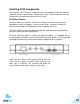
FLX Dialer The FLX Dialer equips the user with an intuitive and interactive tool for configuring and operating the FLX System. The Dialer is not only used to make and answer conference calls, but it is also used for configuring the system settings, having a call using the handset, and monitoring the system components. The FLX Dialer, shown below, is composed of several parts such as a color LCD screen, a compilation of buttons, and a microphone and handset speaker.
FLX Speaker The FLX Speaker, shown below, is a wireless active omnidirectional speaker that has been designed and optimized specifically for use with the FLX Conferencing System. The Speaker is equipped with a pairing button on the bottom and 4 LED indicators on the top to display the activity of the Speaker and the mute status of the system. The Speaker can operate in or out of the Charger Base during conference calls.
FLX Microphones The FLX Microphones provide a sleek and unobtrusive form factor allowing for closer proximity to the participants and creating the best audio available to the far end. They are equipped with a button for pairing and muting, an LED indicator to display mute status and battery charge level, and an internal buzzer to warn if the Microphones have lost connection to the Base Station.
Initial Setup After unpacking the FLX2 Conferencing System, there are a few initial setup tasks that must be performed before a call can take place or any system configuration can be changed. Connecting System Cables The FLX2 Charger Base has a power supply that needs to be connected, as shown below. In addition, the Base Station needs to be connected to the network using the provided Ethernet cable before a conference call can be made.
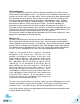
network values like IP Address, Subnet Mask, Default Gateway, and DNS Servers. You will need to restart the phone for any changes you made in this section to take effect. If you are using DHCP, you can go to the System Info menu, and select About System. The assigned IP address for the FLX will be shown here. Independent on how the IP address of your system was assigned, the FLX phone has to be configured to work in your VoIP environment and communicate with your IP PBX.
call, as well as the Speaker and Microphones, are controlled by the FLX Dialer. The user can switch between ‘speaker mode’ and ‘handset mode’ while in a call. Handset Mode Handset mode allows a telephone call to take place through the handset speaker and microphone located in the FLX Dialer. This allows a single user to make and receive a private call. It also provides the ability for the FLX2 System to act as a personal desk phone. The Microphones and Speaker are not used during a handset call.
NOTE: When using the FLX connected through the AUX IN and AUX OUT to another device, only the FLX speaker can be used. All other speakers, e.g. in a television set, must be turned off. To avoid audio problems, any Echo Cancellation provided on the Video Conferencing unit should be switched off. NOTE: For security reasons, Microphones will not send any audio signal to the AUX OUT connector when in the charger. To receive audio signal on the AUX OUT, microphones have to be taken out of the Charger Base.
to this phone will be handled in the switch as defined in there, e.g. sent to voice mail, The Home screen also provides information on new voice mails for the extension (if available), and on missed or rejected calls.
Placing a VoIP Call 1. From the home screen on the FLX Dialer enter the phone number to be called. 2. Once the number is entered completely, press the green ‘call’ button to initiate the phone call. 3. If any Microphones are out of the Charger Base and active, the call will default to ‘speaker mode’ and will be identified by the ring tone being played out of the Speaker. 4. If no Microphones are outside the Charger Base the call will default to ‘handset mode’ and the call will take place on the FLX Dialer.
Answering an Incoming Call 1. When the FLX2 System identifies an incoming call, it will play the ring tone through the FLX Speaker. If the Dialer is not in the Charger Base it will play a ring tone, too. 2. The FLX Dialer will display the caller ID information for the incoming call. The yellow phone symbol represents an incoming call, in this case on line one. 3. A call can be answered in one of three fashions. a. Press the Green ‘Call’ button or the ‘Answer’ key on the FLX Dialer. b.
Ending a Telephone call 1. A call can be ended in two fashions. a. Press the Red ‘End Call’ button on the FLX Dialer during a call. b. Place the Dialer in the charger. (‘Handset mode’ only) 2. When a call is ended the home screen is shown again. 3. Microphones not in the Charger Base will maintain their mute states (muted / unmuted) when a call is ended, and will start in this state when another call is made. Calling a Directory Contact 1. A directory contact can be called in one of two ways. a.
Muting a Call 1. In handset mode, the ‘Mute’ and ‘UnMute’ key will mute/unmute the FLX Dialer microphone, not the wireless Microphones. 2. In speaker mode, the ‘Mute’ and ‘UnMute’ key will mute/unmute all wireless Microphones. NOTE: If the setting ‘All Mic Mute’ is OFF, the Microphone mute buttons will be locked while the Master Mute is active. The Master Mute can only be deactivated via the FLX Dialer. Once deactivated, the Microphones will return to their previous mute state.
Conference Call There are two ways to start a conference call: 1. Press the ‘Enter’ key to access the Active Call Menu and select ‘Conference’. 2. Create the second call by selecting Dialer, Contacts, or Recent. 3. Initiate the second call. 4. After the second call has been established, merge the two calls by pressing the left arrow key, which switches the dialer screen back to Active Call (1), and then press the ‘Join’ key. OR 1.
Component behavior in and out of the Charger Base Each system component will respond differently when placed in or out of the charger during an active telephone call. The following is a description of what can be expected. Dialer When the Dialer is placed into the Charger Base during a call in ‘speaker mode’, the call will not be affected and the Dialer will enter its charging mode.
Bluetooth The FLX2 System is equipped with a Bluetooth interface allowing a call to be placed through a cell phone, computer, or 3rd party Bluetooth device. The FLX Microphones and Speaker then act as the Microphone and Speaker for that call. The FLX2 System only supports the Hands Free Profile for Bluetooth 2.0 or newer. Should the application on the computer, cell phone, or other 3rd party device require other profiles to be supported, FLX cannot act as the Speaker and Microphone for that application.
Adding a Device 1. Go to the Menu Bluetooth. Select ‘Discovery Mode’ to activate Bluetooth and accept Bluetooth Request from other devices. 2. The FLX Dialer displays “This device is visible to other devices in range for 3 minutes” 3. The discovery mode screen will read “System in discoverable Mode, Start Scan From BT Device. System Name: ” 4. Scan for devices from the Bluetooth device you want to connect to the FLX2 System. 5.
Viewing Device Details 1. Go to the Menu Bluetooth. Select ‘Device List’. 2. Select desired device and press the ‘Enter’ key or the ‘Select’ key to view device details 3. Device Information screen is shown with device name, address, BT version, and date/time the device was first connected. Removing a Device 1. Go to the Menu Bluetooth. Select ‘Device List’. 2. Select desired device and press the ‘Enter’ key or the ‘Select’ key. 3. Press the ‘Option’ key 4.
Setting Device Trust Level 1. Go to the Menu Bluetooth. Select ‘Device List’. 2. Select the desired device and press the ‘Enter’ key or the ‘Select’ key to view the device details. 3. Press the ‘Option’ key and then select ‘Options…’. 4. Choose either ‘Auto-Connect’ or ‘Ask’ depending on the trust level you want to set for the Bluetooth Device. Making a call via Bluetooth 1. With the Bluetooth connection enabled, dial a number from the Bluetooth device.
Video Conference Collaboration The FLX2 System is equipped with balanced analog audio input and output to be connected to 3rd party video or PC conferencing system. This allows the FLX Microphones and Speaker to be used as Microphones and Speaker for video calls. It also provides Acoustic Echo Cancelation and Noise Control to the video call. Connecting a Video Conference System In the advanced audio setting (see page 43), change the Aux Audio setting for Aux Out to MIC.
Mixing the audio signals As discussed earlier, Audio and Video, or Bluetooth and Video calls can be made simultaneously from a FLX system, requiring FLX to mix the audio of the different inputs to go to the different outputs. In the Audio Controls menu, available from the main menu and the Active Call Menu, the Audio Mixer menu is offered. This menu offers three different audio mixer settings, based on the output medium.
FLX2 System Configuration There are many features to the FLX2 System that can be modified and configured using the FLX Dialer. The following is a list of those features and their options.
Recent Calls The Recent Calls call log stores the contact information from calls placed or received, allowing the user to review recent calls, redial a recent call, or store a recent call in the system directory. Recent Call Log 1. Access recent call log by browsing: Menu Recent Calls 2. The recent call list is sorted chronologically with the most recent call at the top. 3.
View Recent Call Information 1. Access the recent call log by browsing: Menu Recent Calls or pressing the green ‘Call’ button while no call is in progress. 2. You can view a recent call one of two ways: a. In the recent call list, select the entry you want to view, and press the ‘View’ key. This displays more information for the recent call you selected. b. In the recent call list, press enter to bring up the Options menu. Select ‘View Recent Call’ to display more information for the call you selected.
Delete Call History 1. Access the recent call log by browsing: Menu Recent Calls or pressing the green ‘Call’ button while no call is in progress. 2. In the Recent Call menu, press ‘Enter’ to open the Options Menu. 3. In the Options Menu select ‘Delete Redundant’ to delete redundant call history information, or select ‘Delete All Calls’ to delete all call history information. 4. Press ‘Yes’ to delete the information when prompted for confirmation.
Edit a Contact 1. Browse to the Contacts menu: Menu Contacts, scroll to the desired contact, and select ‘View’ to access the contact. 2. The contact screen shows the current name and number. Pressing the ‘Edit’ key will open the Edit Contact menu. 3. In the Edit Contact menu, select ‘Edit Info’ to edit the selected contact. 4. Edit the name in alphanumeric mode. Pressing ‘Clear’ will delete a character to the left of the cursor.
Search for Contact 1. Browse to the Contacts menu: Menu Contacts. 2. Use the alphanumeric keys to apply a filter a. Once a key is pressed the title line will read ’Contact()’ and display the characters being typed. b. The search string can be up to 5 characters long. c. In this mode the ’Clear’ key will delete the last character in the filter field. 3. Only contact items that satisfy the filter will be shown in the contact screen.
Set Speed Dial 1. Browse to the Contacts menu: Menu Contacts, scroll to the desired contact, and press the ‘View’ key to access the contact. 2. The contact view screen shows the current name and number. Pressing the ’Edit’ key will open the Edit Contact menu. 3. In the Edit Contact menu select ‘Edit Speed Dial’. 4. Scroll to the desired speed dial number and press the ’Set’ key. 5.
Ringer 1. Browse to the Ringer menu: Menu Audio Controls Ringer. 2. Choose ‘Ringer Volume’ in the Ringer Settings menu to adjust the Ringer Volume. 3. Press the up and down buttons to increase and decrease the volume. 4. Choose ‘Ring Tone’ in the Ringer Settings menu to select a ring tone. 5. Use the up and down buttons to select a ring tone, and press enter to set the selected ring tone. 6. The selected ring tone is shown in yellow upper case letters. Equalizer (EQ) 1.
Device Status 1. Browse to Device Status: Menu Device Status. 2. The Device Status screen shows status for the Microphones and the Speaker. NOTE: The device status list is colorized. If a device is charging or off, it will appear white. If a device is fully charged or has more than 50% battery remaining, it will appear green. Once the battery level of a device drops below 50% it will appear orange in the device status list. A critical battery status will appear red.
Bluetooth The ‘Bluetooth’ menu has been explained earlier in this manual on page 26. Home When selecting the ‘Home’ menu item, the Dialer will go back to displaying the home screen. The same effect can be achieved by pressing the ‘Return’ key, or the red ‘End Call’ button. Call When selecting ‘Call’ in the menu, the Dialer will open the Dialer menu, allowing entering and dialing a number.
Date/Time 1. Browse to the Date/Time menu: Menu Setup Set Date/Time. 2. To set the date or time, select either the ‘Set Date’, or ‘Set Time’ option, and press either ‘Enter’ or ‘Select’. 3. Edit time and date (month/day/year) using the numeric keys and the left and right buttons. The ‘Done’ key will store the value; ‘Cancel’ will discard any changes you entered. 4. To change the use of the network time, select the ‘Netwrk Time ON/OFF’ option. You change the setting by pressing the ‘Select’ key.
Advanced Setup The following is a list of advanced configuration settings that are protected by a 4 digit password for administrator access only. The default password is 7386 (revo). This password should be changed by the system administrator. Please ensure that you take note of the changed password. Advanced Audio Browse to Advanced Audio menu: Menu Setup Advanced Setup Advanced Audio. Mic Audio The ‘Mic Audio’ allows controlling the Microphones. 1.
Aux Audio ‘Aux Audio’ is to control the AUX In and AUX Out connectors on the base. 1. Aux In ON/OFF and Aux Out ON/OFF allow enabling / disabling the Aux connectors of the FLX phone. 2. Aux In Level allows changing the level of the Aux In signal. 3. Aux Out Level allows changing the level of the Aux Out signal. 4. Aux Out – MIC / LINE allows setting the level of the Aux Out connectors to either Mic level or Line level.
Admin Settings The Admin Settings menu allows changing settings that are related to general system settings. Setting System Name 1. Go to Menu Setup Advanced Setup Admin Settings Set System Name. 2. Change the current System Name to the new name, and press Enter. Reset Defaults 1. Go to Menu Setup Advanced Setup Admin Settings Reset Defaults. 2. Resetting defaults will revert back to factory defaults.
Web Access ON / OFF Web Access OFF allows you to disable the web interface into the FLX. If Web Access is set to off, any attempt to open the web interface will be declined. Please be aware that if the web interface is switched off, it can only be restarted from the phone. Pairing All FLX2 wireless components are paired before the system is shipped, providing much of the system setup already completed.
Speaker 1. To pair a Speaker first turn it off by pressing and holding the button on the bottom of the Speaker until you hear the Speaker shut-off or the LEDs turn off. 2. Ensure that the Base Station is plugged in and powered up. 3. On the Dialer, browse to the Pairing menu: Menu Setup Advanced Setup Pairing. 4. Select SPK 1 (Speaker 1) and press the ‘Enter’ or ‘Pair’ key to enter pairing state. 5. The screen will display ‘Pairing Speaker 1’. 6.
LED Pairing Indicators: Speaker Indicator Steady Red Slow red- green flash Green flash Microphone Indicator Steady Red Slow red – green flash Green flash Status Speaker is in Pairing Mode, either waiting or pairing in progress Pairing failed or timed out Pairing successful Status Pairing Mode, either waiting or pairing in progress Pairing failed or timed out Pairing successful Network Settings 1. Browse to the Network Settings menu: Menu Setup Advanced Setup Network Settings. a.
Web Interface The FLX web interface provides access to advanced configuration settings, call statistics and system logs. Web access can be enabled or disabled from the FLX Handset, and the web interface is password protected using the same password that is required to access Administrator settings on the FLX Handset.
Enter the administrator password and click Login. After logging in, the FLX Home page will appear. The FLX web interface is organized into three categories: Home, User and Administrator. Choose any one of these categories by clicking on the corresponding link in the upper right corner. Home Page The Home page shows general information about the system as shown below. The Product field is a brief description of the FLX phone to which you are connected.
User Settings In the upper right corner click the User link to access the User settings. The User Menu will appear on the left side of the page showing these options: • • • • • Audio Call Forwarding Date/Tim Restart Logout Choose a User Menu option to show the corresponding page. Audio The Audio page can be used to configure audio settings and audio mixer settings of your FLX. These settings are also available on the Handset.
Audio Mixer The settings below can be changed at any time during a call. Speaker Mix The Speaker Mixer specifies the mix between AUX IN and the phone input to be played back on the speaker. It is a sliding scale from -8 (favoring phone) to +8 (favoring AUX IN). Phone Out Mix The Speaker Mixer specifies the mix between the microphones and AUX IN to be transmitted to the far end during a call. It is a sliding scale from -8 (favoring microphones) to +8 (favoring AUX IN).
Date/Time The Date/Time page is used to specify how the date and time are to be set, either automatically or manually, and the time zone and Daylight Saving Time rules for your locale. Below is an illustration showing the Date/Time page settings followed by a table describing each field.
Week Day Hour For the specified month, select the week in which DST changes. For example, if DST changes on the second Sunday of the selected month, choose “Second.” Select the day on which DST changes, for example, Sunday. Select the hour at which DST changes. For example, if DST changes at 2:00 a.m., choose 2. Restarting the Phone To restart the phone, choose Restart from the User menu or Administrator menu on the left of the page. On the Restart page click the Restart button as shown below.
• • • • • • • RF Settings Access Control Import/Export System Log Call Status Restart Logout Choose an Administrator Menu option to show the corresponding page. Network Settings Use the Network Settings page to specify how IP addressing is to be determined for the phone connected to the IP network.
Static IP Settings Static IP Address The Static IP Address is the IP address that the network administrator has assigned to the phone. Subnet Mask Subnet Mask is used to determine the subnet to which the phone belongs, for example, 255.255.255.0. Default Gateway The Default Gateway is the phone’s default router on the IP network. It is usually the router connecting the internal network with the outside network. Domain Name This is the network domain name.
The table below describes the SIP Registration settings. Different IP PBX providers might use different names in their setup. The descriptions below will help you in mapping the FLX fields to your IP PBX fields. SIP Registration Registrar This is the IP address or DNS name of the SIP registrar server. Use Proxy for Use this option to indicate whether or not the SIP proxy server(s) Registration specified in the Outbound Proxy field should be used when registering.
SIP Settings Use the SIP Settings page to configure settings related to SIP sessions, as shown in the illustration below. After changing any of these settings, the phone must be restarted for the changes to take effect. SIP Settings Use SIP session timers Session timers expiration period Specify the preference for using SIP session keep-alive timers.
period to be used for the session. Session timers This is the minimum session timer expiration period that FLX will minimum accept when negotiating the expiration period with the remote expiration period phone. It is measured in seconds; the default is 90. Require reliable Select this option to implement reliable SIP provisional responses. SIP provisional By default the setting is unchecked. SIP is a request-response type response of protocol with two types of responses: provisional and final.
DTMF Signaling Method Select the signaling method for transmitting DTFM tones, either via RTP (RFC2833) or SIP INFO messages. The default is RTP. Transport Use the web interface’s Transport page to manage transport and Network Address Translation (NAT) settings, and to enable or disable Quality of Service (QoS). The illustration below shows the Transport page. After changing any of these settings, the phone must be restarted for the changes to take effect.
Transport Settings Use SRTP Use this setting to control Secure Real-time Transport Protocol (SRTP) usage. These are the available options: Disabled – Do not use SRTP; always use RTP. This is the default setting. Optional – Use the optional disposition for SRTP in SDP. If the remote end supports SRTP, then use SRTP; otherwise, use RTP. Mandatory – Force use of SRTP. If the remote end does not support SRTP, the call does not connect.
Maximum number of ICE host candidates Disable RTCP component in ICE Enable TURN relay with ICE TURN Server TURN Username TURN Password Use TCP connection to TURN server QoS Enable QoS remote nodes), FLX sends STUN binding requests as part of the media connectivity tests. When a candidate is nominated for use, a STUN binding request is sent with a flag indicating that the candidate pair is nominated.
Differentiated Services Code Point (DSCP) in the IP header is set to 24 (0x18). For layer 2, IEEE 802.1p tagging is supported. This option is unchecked by default. Media Settings Use the Media page to specify the preferred audio codecs and other audio stream processing preferences as shown in the illustration below. After changing any of these settings, the phone must be restarted for the changes to take effect.
Disable silence detector/voice activity detector Jitter buffer maximum delay Select this option to disable silence detector/voice activity detector (VAD). VAD is a technique used in audio processing to detect the presence or absence of human speech. Disabling VAD is sometimes useful to work around NAT problems. This option is unchecked by default. Specify the jitter buffer maximum delay in milliseconds. Leave the field empty or specify -1 to use the default. The FLX default is 500 ms.
Advanced Audio Settings Use the Advanced Audio Settings page to specify microphone mute behavior, AUX audio in and out settings, and Acoustic Echo Cancellation (AEC) settings. The illustration below shows this page. The settings and options on this page reflect the same settings as can be done on the handset, allowing remotely setting and managing the phone behavior.
Aux In Level, Aux Out Level Aux Out Mic/Line Omni AEC, Directional AEC, Lapel AEC The “Aux In” and “Aux Out” settings are used to change the level of the Aux In and Out signals. The range is 1-15. Use Aux Out Mic/Line to set the level of the Aux Out connectors to either Mic level or Line level. The AEC options allow controlling the Acoustic Echo Cancellation levels of the different microphone types (Omni, Directional, or Lapel). The range is 0-8, with 8 the most aggressive echo cancellation.
Access Control Password Recent Call Enabled Web Access Enabled The password is used to control access to the web interface and the advanced Administrator settings on the FLX Handset. The password must be four digits. The default password is 7386. This password should be changed by the system administrator. Please ensure that you take note of the changed password. Use the Recent Call Enabled option to enable or disable the Recent Calls list on the FLX Handset. The default setting is On.
To export FLX configuration settings, click the Export button. A File Download window will appear prompting you to open or save the file as shown below. Click the “Save” button to save the file to the desired location. To import a configuration file, open a web session and login to the target phone to be configured, and select the Administrator > Import/Export page.
Your web browser should indicate the download progress. When the download is complete, you will be prompted to save the compressed configuration file. The file name will include the IP address of the FLX and a date and time stamp, for example, log10.134.123.101-120131-210112.tar.gz. You should be able to email the compressed file as instructed by the support staff. The support staff may also ask you to select the option to Enable Verbose SIP Logging.
Power On/Off the System Components During normal use and operation of the FLX2 System, there is no need to turn off any part of the system. However, if the system is going to be stored without the Charger Base powered on, then each component should be powered off until further use. Dialer On/Off To power off the FLX Dialer, hold down the red ‘end call’ soft key until the device asks whether you want to shut it down. Confirm this by pressing ‘Yes’. To turn the Dialer back on, either: 1.
Battery Exchange The rechargeable batteries in the different FLX components can all be exchanged. Please note that only Revolabs approved batteries should be used for the replacement. The following sections explain how to change the batteries in the different components. We recommend charging any component for 8 hours after exchanging the battery.
Take the current battery out of the handset as shown, and replace it with the new battery. Please ensure that the connectors on the battery are lined up with the connectors inside the dialer. Speaker To change the rechargeable battery in the FLX speaker you will need to use a screwdriver to loosen the screw on the bottom of the speaker. Once the screw is loose, the bottom door of the speaker will open, revealing the rechargeable battery pack.
Polycom HDX9000 Polycom QDX6000 Polycom FX Polycom VSX7000e Polycom VSX7000s Polycom VSX8000 Tandberg Tandberg Tandberg Tandberg Tandberg Tandberg Tandberg Sony Sony Sony Sony Sony C20 C40 C60 C90 Edge 3000 MXP 6000 MXP USB Audio Adapter XG-80 PCS-G70 PCS-HG90 PCS-G50 PCS-1 Panasonic KX-VC600 Panasonic KX-VC500 Panasonic KX-VC300 PC Audio Main Line Input L Main Line Input 1 Mono Line Input Main Line Input 1 Main Line Input 1 Main Line Input L Mic Input Mic Input Mic Input Mic Input Mic
Troubleshooting Warning Messages Speaker / Microphone Link Lost If a FLX Microphone or FLX Speaker loses connection to the FLX2 Base Station, the LED indicator will begin flashing a sequence of red – yellow - green - yellow and start emitting a beeping notification. To reconnect the Microphone or Speaker move it back into range of the Base Station.
2. 3. 4. 5. 6. the Base Station. All components should automatically connect to the Base Station after a few seconds. The Base Station is powered up, but the Status LED indicates a fault has happened by missing every fifth green double flash. Power down and power up the Base Station. All components should reconnect to the Base Station after a few seconds.
Device LED Indicator Status Two Red flashes every second On, connected, battery charged, individually muted Red flash every second On, connected, battery charged, Master Mute or “All Mic Mute” is ON, microphones muted Alternating Yellow - Green flash On, connected, battery low, un-muted Alternating Yellow - Double-Red flash On, connected, battery low, individually muted Alternating long Red - Yellow flash Flashing Yellow – Red – Yellow – Green Alternating slow Red - Green flash Steady Red Groups o
Device LED Indicator Status Alternating slow Red - Green flash Speaker is not paired to a Base Station Speaker is powered off: Off o Speaker is not seated properly o Charger tray is powered off Speaker not in Charger Base Off Speaker is powered off o Connected, no call in progress, Microphones in Charger Base o Connected, no phone call in progress, Microphone(s) outside of the Charger Base Green flash every second unmuted o Connected, call in progress, Microphones are not muted using All Mic Mute or Mast
Reset to Factory Defaults See page 41 for a description on how to reset the FLX2 Conference Phone back to its factory defaults. Technical Specifications Models The Revolabs FLX2 VoIP System is available with a variety of configurations to provide the best audio capture in the industry. The following is a list of the available models. All of these models are SIP enabled and require an IP connection.
Microphones Dimensions Microphones Weight Bandwidth Battery life (talk time) Charge time 94.2 x 24.6mm x 18.5 mm (omnidirectional Microphone) 28.6g (omnidirectional Microphone) 80-11,000 Hz from Microphone to Analog OUT. This is reduced for VoIP calls based on the bandwidth supported by the selected transport codec.
Regulatory Information FCC Notice to Users Users are not permitted to make changes or modify the equipment in any way. Changes or modifications not expressly approved by Revolabs, Inc. could void the user’s authority to operate the equipment. This device complies with Part 15 of the FCC Rules.
Restricted use with certain medical devices Hearing Aids Some devices may interfere with some hearing aids. In the event of such interference, you may want to consult with your hearing aid manufacturer to discuss alternatives. Other Medical Devices If you use any other personal medical device, consult the manufacturer of your device to determine if it is adequately shielded from RF energy. Your physician may be able to assist you in obtaining this information.
E C Declaration of Conformity Manufacturer’s Name: Manufacturer’s Address: Revolabs 144 North Road, Suite 3250 Sudbury, MA 01776 U.S.A.
Limited Warranty and Limitation of Liability Limited Warranty Revolabs warrants to the end user (“Customer”) that this product will be free from significant defects in workmanship and materials, under normal use and service, for one year from the date of purchase from Revolabs or its authorized reseller provided the customer provides proof of purchase that demonstrates that the product is still within the warranty period and contacts Revolabs customer service, regarding warranty claims, within the warranty
Limitation of Liability TO THE FULL EXTENT ALLOWED BY LAW, REVOLABS EXCLUDES FOR ITSELF AND ITS SUPPLIERS ANY LIABILITY, WHETHER BASED IN CONTRACT OR TORT (INCLUDING NEGLIGENCE), FOR INCIDENTAL, CONSEQUENTIAL, INDIRECT, SPECIAL, OR PUNITIVE DAMAGES OF ANY KIND, OR FOR LOSS OF REVENUE OR PROFITS, LOSS OF BUSINESS, LOSS OF INFORMATION OR DATA, OR OTHER FINANCIAL LOSS ARISING OUT OF OR IN CONNECTION WITH THE SALE, INSTALLATION, MAINTENANCE, USE, PERFORMANCE, FAILURE, OR INTERRUPTION OF ITS PRODUCTS, EVEN IF RE
GPL LICENSED SOFTWARE The following GPL licensed software is used in this product and is subject to the GNU General Public License version 2 (GPLv2) License Agreements included as part of this documentation: uClinux 2.6.26 BusyBox 1.2.2 Source code for this software can be obtained by contacting Revolabs at support@revolabs.com. GNU GENERAL PUBLIC LICENSE Version 2, June 1991 Copyright (C) 1989, 1991 Free Software Foundation, Inc.
Finally, any free program is threatened constantly by software patents. We wish to avoid the danger that redistributors of a free program will individually obtain patent licenses, in effect making the program proprietary. To prevent this, we have made it clear that any patent must be licensed for everyone's free use or not licensed at all. The precise terms and conditions for copying, distribution and modification follow. TERMS AND CONDITIONS FOR COPYING, DISTRIBUTION AND MODIFICATION 0.
itself is interactive but does not normally print such an announcement, your work based on the Program is not required to print an announcement.) These requirements apply to the modified work as a whole. If identifiable sections of that work are not derived from the Program, and can be reasonably considered independent and separate works in themselves, then this License, and its terms, do not apply to those sections when you distribute them as separate works.
If distribution of executable or object code is made by offering access to copy from a designated place, then offering equivalent access to copy the source code from the same place counts as distribution of the source code, even though third parties are not compelled to copy the source along with the object code. 4. You may not copy, modify, sublicense, or distribute the Program except as expressly provided under this License.
consistent application of that system; it is up to the author/donor to decide if he or she is willing to distribute software through any other system and a licensee cannot impose that choice. This section is intended to make thoroughly clear what is believed to be a consequence of the rest of this License. 8.
LIABLE TO YOU FOR DAMAGES, INCLUDING ANY GENERAL, SPECIAL, INCIDENTAL OR CONSEQUENTIAL DAMAGES ARISING OUT OF THE USE OR INABILITY TO USE THE PROGRAM (INCLUDING BUT NOT LIMITED TO LOSS OF DATA OR DATA BEING RENDERED INACCURATE OR LOSSES SUSTAINED BY YOU OR THIRD PARTIES OR A FAILURE OF THE PROGRAM TO OPERATE WITH ANY OTHER PROGRAMS), EVEN IF SUCH HOLDER OR OTHER PARTY HAS BEEN ADVISED OF THE POSSIBILITY OF SUCH DAMAGES.