
Manual


User’s Manual
4
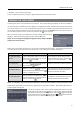
Connecting the Video Input
Connect the RJ-12 cables from the modular cameras to
the modular RJ-12 connectors.
Connect the coaxial cables from the video sources to the BNC Video In connectors.
(16-Channel Model Only)
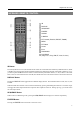
Connecting the Monitor
A VGA connector is provided so that you can use a standard, multi-sync computer monitor as your
main monitor. Use the cable supplied with your monitor to connect it to the DVR. The VGA monitor
is automatically detected when you connect it.
NOTE: It is possible that the DVR will not automatically detect a VGA monitor if the monitor does not support
the auto detect function. In this case, press and hold the DISPLAY button on the remote control for 5 seconds or
longer to switch the video output to VGA out. Pressing and holding the button for 5 seconds or longer again returns
to the composite video output mode.
If you prefer to use a standard CCTV monitor, connect it to the Video Out connector.
NOTE: The DVR does not support simultaneous operation of a CCTV and a VGA monitor.
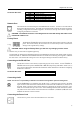
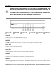
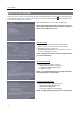
Connecting Alarms
NOTE: To make connections on the Alarm Connector Strip, press and hold the button and insert the wire in the
hole below the button. After releasing the button, tug gently on the wire to make certain it is connected. To
disconnect a wire, press and hold the button above the wire and pull out the wire.
AI 1 to 16 (Alarm-In): You can use external devices to signal the DVR to react to events. Mechanical or electrical
switches can be wired to the AI (Alarm-In) and GND (Ground) connectors. The threshold voltage for NC (Normally
Closed) is above 4.3V and for NO (Normally Open) is below 0.3V, and it should be stable at least 0.5 seconds to be
detected.
GND (Ground): Connect the ground side of the alarm input and/or alarm output to a GND connector.
NOTE: All the connectors marked GND are common.
NC/NO (Normally Closed/Normally Open): Connect the device to the C (Common) and NC (Normally Closed)
connectors or C and NO (Normally Open) connectors. NC/NO is a relay output which sinks 0.5A@125VAC (NC) and
1A@30VDC (NO).
ARI (Alarm Reset In): An external signal to the Alarm Reset In can be used to reset both the Alarm Out signal and
the DVR’s internal buzzer. Mechanical or electrical switches can be wired to the ARI (Alarm Reset In) and GND (Ground)
connectors. The threshold voltage is below 0.3V and should be stable at least 0.5 seconds to be detected. Connect the
wires to the ARI (Alarm Reset In) and GND (Ground) connectors.