
Installation Instructions
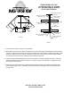

11-3/4"
12"
9-1/4"
12"
10-3/4"
17" FRAME
(16"FRAMELESS)
SHAFT
(6470-96-2208-26)
UPPER PIVOT SUPPORT
(6000-91-2)
LOCKING SCREW
(M2405-409-2)
SHAFT LOCKING SCREW
(M2408-409-2)
FIGURE 2
BOTTOM POSITIONER
(6260-95-2)
SHELF SUPPORT
(6470-07-2)
FIGURE 1
INSTALLATION INSTRUCTIONS
20" REVOLVING D-SHAPE
PREMIERE CHROME LAZY SUSANS
INSTALLATION TEMPLATE
ON REVERSE SIDE.
UPPER SHAFT ASSEMBLY
(6470-93-0904-26)
UPPER POSITIONER
(6260-95-2)
SHAFT LOCKING SCREW
(M2408-409-2)
1. The dimensions shown in Figure 1. are minimum.
2. With bottom and upper pivot supports installed (see reverse side), begin assembling the shelves and the
main shaft. Working from bottom up, inside the cabinet space, slide the upper shelf onto the shaft. Slide
the upper positioner onto the shaft and temporarily tighten the screw with the positioner approximately
15" from the bottom of the shaft. Slide the bottom shelf onto the shaft.
3. Insert the upper shaft assembly into the top end of the shaft. Loosely install the lock screw. Insert the
shaft/tray assembly into the bottom positioner. Extend the upper shaft assembly to engage the upper
pivot support (See Figure 2).
4. Adjust the upper shelf position by grasping and supporting the upper shelf positioner assembly while
loosening the locking screw. Rotate the positioner and shelf into alignment and securely tighten the
locking screw.