
Installation Instructions


2
INSTALLATION INSTRUCTIONS: CHARGING DRAWER
Customer Service: 800-626-1126 | rev-a-shelf.com
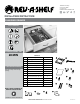
13/16”
(21mm)
3/32”
(2mm)
1-1/4”
(32mm)
5/8”
(16mm)
1-1/32”
(26mm)
15/32”
(11.6mm)
9/16”
(14mm)
13/32" (10 mm)
1-15/32" (37 mm)
A
B
11/32" (9 mm)
1/8" (3 mm) Setback
Inside cabinet depth
Left Side Screw Locations
Runner length
1-1/4" (32 mm)
Frameless and
face frame
Face frame
only
Right Side Screw Locations
I-4WCDB18-0718
I-4WCDB18-0718
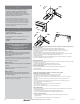
FIG. C
FIG. D
1st
3rd
5th
2nd
4th
FIG. E
FIG. F
Attach the (5) wire clamps and the
(5) 1/4 -14 x1/2” screws onto the
arm. Screw in a wire clamp on the
rst, third, and fth hole on the
left bar and screw a wire clamp
into the second and fourth hole on
the right bar (See Figure D).
Once the screws and clamps are in
place, lift up and feed the outlet
wire through the clamp.
NOTE: For frameless application,
skip to Step 2.
Attach the rear Blum brackets on
the back of the cabinet using (4)
#8 x 5/8” wood screws for each
bracket (See Figure E).
Place (2) screws in the top row
in each of the two corners and
place (2) screws in the fourth row
as indicated by the dark circles in
Figure E.
INSTRUCTION FOR
ATTACHING SLIDES AND
INSTALLING THE DRAWER
STEP 1
Attach the large bracket to the
LEFT Blum slide by unscrewing the
(2) screws that are already in the
bracket (See Figure F).
STEP 2
Install the right and left Blum
triggers on the bottom of the
drawer using (4) #6 x 1/2” pan
head screws (See Figure A).
STEP 1
Install the cable carrier arm via
the (2) pre-drilled holes on the left
side of the drawer box using (2) #8
x1/2” truss head screws.
NOTE: Make sure hinge folds as
depicted in Figure C.
STEP 2
Install the gure 8 brackets onto
the front of the drawer using the
screws that come inside of the
same bag as the gure 8 brackets
(See Figure B).
STEP 3
FIG. A
FIG. B
STEP 4
Attach both the left and right Blum
slides to the cabinet by sliding
them onto their corresponding rear
brackets (See Figure G-1). Screw the
slides to the face frame cabinet with
(2) #8 x 5/8” wood screws for each
side (See Figure G-2).
NOTE: Frameless applications will
use (2) #8 x 5/8” wood screws on
the left side and (3) #8 x 5/8”
wood screws on the right side (See
Fig. G-3).
STEP 3
FIG. G-1
FIG. G-3
FIG. G-2
3
Face frame
Frameless