
Servo-Drive

2. Once the servo mount has been located with the front two mounting
holes, install the remaining (3) No. 8 x ¾ screws securing the mounting
plate to the cabinet oor.
448 SERVO KIT INSTRUCTION SHEET
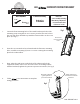
1. Locate the front mounting holes of the metal bracket under the slide
mounting straps using the No. 8 x ¾ screws provided. The two holes in
the rear slide strap should line up with the front two holes on the servo
plate. (See Fig 1)
3. Next, adjust the jack screws to the back of the cabinet wall to help
support the action of the servo. Once the screws are making contact
with the back wall, tighten the jam nut to prevent movement. (See Fig 2)
Fig 1
Fig 2
TOOLS REQUIRED:
Estimated Assembly:
10 min
Parts List:
• Servo assembly (including
Blum wiring components)
• Servo instruction sheet
• (5) No 8 x ¾” screws
I-448-SERVOKIT-0512
7/16”
4. Follow servo instructions to complete
wiring procedure.
Use the two
center mounting
holes
Once fully adjusted,
tighten jam nut to
prevent movement.
Adjust until the jack
screw hits the back wall
of cabinet.