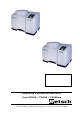
Operating Instructions Ball Mills Type PM100 / PM200 / PM100cm Retsch GmbH, 42781 Haan, Retsch-Alle 1-5, Germany, 10/31/2014 0006
Information on these operating instructions .................................. 4 Warnings ..................................................................................... 4 Repairs ........................................................................................ 4 Safety .................................................................................................. 5 Safety instructions .......................................................................
Speed .......................................................................................... 29 Interval ........................................................................................ 30 Start time ..................................................................................... 31 Opening mechanism ................................................................... 31 Energy ......................................................................................... 31 Alarm ................
Information instructions on these operating The present operating instructions for the ball mills of type PM100/200 provide all the necessary information on the headings contained in the table of contents. They act as a guide for the target group(s) of readers defined for each topic for the safe use of the PM100/200 in accordance with its intended purpose. Familiarity with the relevant chapters on the part of each target group(s) of readers is essential for the safe and proper use of the equipment.
Safety The PM100/200 is a modern, high-performance product manufactured by Retsch GmbH. It incorporates the latest technology. The machine is entirely safe in its operation when used for the intended purpose and in accordance with the present technical documentation.
Safety directives summarised, part 1 Safety instructions We reject herewith any and all claims relating to personal injury or material damage that result from the failure to comply with the following safety instructions. Intended use Do not make any modifications to the machine and only use Retsch approved spares and accessories. The conformity to the European guidelines declared by Retsch otherwise loses its validity. It furthermore leads to the loss of all warranty claims.
Safety directives summarised, part 2 Grinding bowl filling level If the filling level of the grinding bowl is too high or too low, the end result will be impaired and the milling set could become damaged (increased wear and tear). Stacking 50ml grinding bowls of type "C" It is not possible to stack 50ml grinding bowls in the PM200. Heating the grinding bowls Please take the action necessary - depending on how dangerous the material you are grinding is - to ensure that people are not exposed to danger.
Confirmation I have read and understood the chapters Foreword and Safety.
Technical specifications Machine type designation: PM100/PM200 Intended use Retsch ball mills are used to grind and mix materials that are soft, medium hard to extremely hard, brittle or fibrous. Dry and wet grinding is possible, grinding with solvents is permissible, although in this case it is essential to observe the supplementary instructions given in the chapter "Wet grinding with easily inflammable materials".
Protective equipment The PM100 and PM200 are equipped with fixtures to automatically close the cover. This prevents the devices being started in an unsafe state. The machines cannot be started unless the cover is closed. It is only possible to open the cover when the machines are at standstill. Operating mode S1 An operating mode with constant loading, the duration of which suffices to reach the state of thermal rigidity. (DIN VDE 0530 T1) Device dimensions Height: Up to approx.
Transport and assembly Packaging The packaging has been adapted to the mode of transport. It corresponds to the generally applicable packaging guidelines. Please retain the packaging for the duration of the warranty since, in case of complaint, returning in unsuitable packaging can jeopardize your warranty claims. Transport During transportation, do not subject the PM100/PM200 to impacts, jolts or vibrations. The electronic and mechanical components could otherwise be damaged.
Requirements for the assembly site Ambient temperature : 5°C to 40°C When the ambient temperature exceeds or falls below that specified, the electronic and mechanical components may be damaged, and performance data changed to an unknown extent.
Serial interfaces Interface to update the software Inactive interface for optional data communication with an external device. Software update required. The interface cables may not be longer than 2.5 m. Longer cables can cause faults in the transmission of data.
Operation Connect the power Ensure that the voltage and frequency of your mains power supply agree with the data plate of the PM100 or PM200. Plug the power cable into the socket at the rear of the device Plug the cable into the mains power socket Turn the main switch on Failure to observe the values on the data plate can cause damage to electronic and mechanical components. The language menu is displayed the first time the PM100/200 is switched on.
Emergency unlocking A key is fixed underneath the unit. This can be used to open the PM100 or PM200 manually in case of a power failure. Lift the unit Remove key S (I) Insert the (S) key into the (O) opening on the right-hand side. (II) To unlock the gear, the key must be pushed in further with some degree of force. While pushing the key in, turn it in a clockwise direction as far as it will go. The cover can now be opened.
Inserting and clamping grinding bowls in the PM100 Before starting the machine ensure that the milling cup is clamped. Milling cup can be ejected, danger of injury and damage to equipment. Wear of safety slider In case of wear at the screws and/or slits as well as an substantially increased play of the safety slider, it should be replaced.
Clean the grinding bowl disk with torsion lock pin 1 Turn the label on the grinding bowl 2 to the same side as the torsion lock pin, the borehole in the grinding bowl is located here. Insert the grinding bowl into the grinding bowl fixture 5 Up = free Pay attention to the torsion lock in 250 and 500 ml grinding bowls. The borehole in the base of the grinding bowl to take up the torsion lock pin is located on the side of the marking areas.
6 4 Insert the counter spanner 6 under the red sleeve 5. The spindle is now unlocked. Turn the three star grip to the right (clockwise) for tightening and to the left (anticlockwise) for loosening. The drive now turns only until a latched bracket 4 is in contact with the counter spanner 6. Easy tightening or loosening is then possible. For the PM200 the counter spanner 6 must be turned 180° and inserted when the grinding bowl fastening device is in the highest lock-in position.
GRINDING BOWL CLAMPED? NO Yes The grinding process starts after this confirmation. This safety instruction can be hidden in the “settings” menu. Make sure the grinding bowl is clamped before you start the machine. The grinding bowl can be hurled out, risk of injury and damage to property! Our recommendation is that you do not hide the safety instruction.
Balancing – only required for the PM100 In order to ensure that the machine runs smoothly, the PM100 must be balanced after the grinding bowl has been inserted and clamped in. K Weight the grinding bowl with cover, ball filling and the material to be ground Move the balancing weight using the knob until edge K on scale S shows the determined weight.
Inserting and clamping grinding bowls in the PM200 Only operate the PM200 with grinding bowls up to a maximum nominal volume of 125ml. In order to avoid unpleasant vibrations, 2 grinding bowls with the same gross weight must always be inserted.
Safety instructions for starting the PM 200 The grinding bowl clamping fixture has proven its worth over many years as an easy-to-manage and reliable appliance. A precondition here both for the operator’s safety and also to ensure that the components have a long service life is that the grinding bowl must be clamped conscientiously.
Suitable grinding bowls for the PM100 The PM100 is only suitable for grinding bowls of the type "Comfort" with a nominal volume of 12-500 ml. They are available in the following materials: Agate Sintered corundum Zirconium oxide Stainless steel Special steel Tungsten carbide The "Comfort" grinding bowl program was developed especially for extreme test conditions, such as long-term trials, high mechanical loadings, maximum speeds and for mechanical alloying.
Suitable grinding bowls for the PM200 The PM200 is only suitable for grinding bowls of type "Comfort" with a nominal volume of 50-125 ml. Grinding bowl filling level Guide values for material volumes and balls Nominal volume 12 25 50 80 125 ml ml ml ml ml Utility volume -5 - 10 5 – 20 10 – 35 15 – 50 ml ml ml ml ml Max.
Grinding bowl identification All grinding bowls of type "C" are easily identified by a marking area SCH1, including the article No. and material. Customer marking of grinding bowls In addition to the aforesaid marking area, you can affix one of the labels supplied (or available as accessories) to an area SCH2 on the grinding bowl; this makes it possible to apply extra markings, such as grinding bowl capacity etc.
Use of the closing device for milling cups After filling the milling cups these must be closed with closing devices available as accessories. For milling cups with material inserts, ceramics or tungsten carbide use only closing devices which support the material insert of the milling cup lid. This is absolutely essential owing to the anticipated internal pressure.
Operation via the PM100/200 display unit A The mills offer new, very userfriendly operating functions. All relevant data can be entered or called up from a graphic display operated with a single button. The menu is multi-lingual. B C D A Designation Display B C D E START key STOP key Key Setting button E Function Displays the menu, the parameter settings, operating information and error messages.
Menu structure of the display unit 1. Level 1 MANUAL OPERATION GRINDING PROGRAM 01 bis 09 2. Level 3. Level 4. Level OPENING MECHANISM YES / NO 5.
Adjustment options via the display menu Please consult the menu structure on this page for the setting options on the display explained below.
00:01 to 59:59 Interval Reverse rotation cannot be set until an interval is set. Minutes:Seconds Reverse rotation YES NO The PM100/200 is started at the pre-selected grinding time, speed and reverse rotation. The machine rotates with the specified interval time in one direction, runs down and then starts immediately after coming to a stand still, without interval break, in the other direction.
Start time Start in Cancel xx h The start can be pre-selected from 01 to 99 h here. The PM100/200 is started at the pre-selected grinding time, speed and reverse rotation after the specified start time has expired. Make certain that the grinding bowls have been securely clamped and balanced before letting the machine start unattended. Even though it is not possible to start the machine without the cover closed, ensure that the cover is closed before letting the machine start unattended.
Start the machine. The process now started takes about 45 seconds. During this time the PM 100 / PM 200 determines the idling energy with the grinding bowl empty at the later operating speed. The PM 100 stops automatically after the idling energy has been recorded and you are requested to fill it with the material to be ground and grinding balls. Determine the increased weight of the grinding bowl filled with material and grinding media.
Contrast / brightness MENU DISPLAY CONTRAST BRIGHTNESS The contrast and brightness can be adapted to the particular user or ambient conditions (sunlight, glare etc.). If the contrast or brightness has been incorrectly set (the display can no longer be read), switch the device off at the main switch, simultaneously hold down the START, STOP and COVER OPEN keys and switch it on again. You will now see the language menu and the values for CONTRAST and BRIGHTNESS have returned to the default settings.
Error messages on the display F01 to F12 F02 The display shows F01 Lock indicator Close cover The error appears when the cover has not been fully closed, or if the trannion magnets have not been recognised. Close the cover The display shows F03 The display shows F04 Problem in the safety circuit of the interlock Close or open cover, should problem remain then interlock faulty Service required! Service required! The error appears when the The error appears when the interlock is defective.
F13 to F26 F13 The display shows F14 Fault speed sensor Service required! The display shows F15 The display shows F16 Problem in the safety circuit of the frequency converter Motor has overheated No START possible Service required! Let motor cool down The display shows F17 The display shows F18 Motor has overheated Was switched off Let motor cool down Problem in the safety circuit of the transformer Continue with STOP Service required! F19 F20 The display shows Overload 110% F21 The display s
General points Cleaning Do not clean the PM100/200 with flowing water. Mortal danger from electric shock Only use a cloth dampened with water. Solvents are not permitted. Maintenance 1 2 3 4 5 The following service work should be performed from time to time, although at the latest once per month, in order to guarantee the operational reliability of your PM100/200: Check roller 1 of the locking trannion for easy running and oil, if necessary, e.g.
Parts subject to wear and tear The operating instructions do not contain any repair instructions. In the interests of your own safety, repairs should only be performed by Retsch GmbH, an authorised representative or by Retsch service technicians. Spider with pressure piece PM100 Art. No. 22.661.0002 Only deployable for PM100. Spider with pressure piece PM200 Art. No. 22.661.0003 Only deployable for PM200. For PM100 2x latching brackets Art.No. 22.623.0001 1x latching brackets SafetySlider Art.No. 22.623.
Safety slider replacement interlock lug PM 100: 22.623.0010 PM 200: 22.623.0011 Copyright Reproducing or distributing this documentation, or utilizing and distributing the contents is not permitted unless Retsch GmbH has given express permission to do so. Violations against this are subject to claims for damages. Changes Technical changes are reserved.
CERTIFICATE OF CE-CONFORMITY Translation PLANETARY BALL MILL PM 100 and PM 200 Certificate of CE-Conformity according to: EC Mechanical Engineering Directive 2006/42/EC Applied harmonized standards, in particular: DIN EN ISO 12100 Security of machines EC Directive Electromagnetic Compatibility 2004/108/EC Applied standards, in particular: EN 61236 Electrical equipment for measurement, control and laboratory use in conjunction with EN 55011 and EN 61000 Additional applied standards, in particular DIN EN
Copyright ® Copyright by Retsch GmbH Haan, Retsch-Allee 1-5 D-42781 Haan Federal Republic of Germany