
User guide


Transport, scope of delivery, installation
16
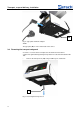
Fig. 9: Mounting the hopper support
• Loosen the locking screw (E).
• Place the hopper support (B) on the rod (G).
• Screw the locking screw (E) tight.
By twisting and sliding vertically, the hopper support makes it possible to place the
feed hopper in the correct position.
Pos: 6.12 /00005 Ü berschriften/ 1.1 Überschrifte n/1.1 Überschrift en BDA/11 Trich ter einsetzen @ 4\mod_13 32402943722 _9.doc @ 27418 @ 2 @ 1
3.13 Inserting the hopper
Pos: 6.13 /00010 Bedienungsa nleitungen Kapitels ammlungen/DR 100_2012/00 06 DR100_201 2 Transport, Lie ferumfang und Au fstellen/DR 100 Trichter einsetzen @ 4\ mod_1332402 621830_9.doc @ 27378 @ @ 1
Fig. 10: Inserting the hopper
Insert the hopper (A) in the support (B).
Pos: 7 /00010 Be dienungsanleitu ngen Kapitelsam mlungen/------- Seitenumbr uch ----------- @ 0\mod_1222344373758_ 0.doc @ 2386 @ @ 1
A
B
<dg
_b
m
"Ak
tuel
leP
ositi
on"
>E
</d
g_b
m
"Ak
tuel
leP
ositi
on"
>
B
G