
User guide


Transport, scope of delivery, installation
15
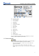
Fig. 7: Locking the vibrating chute in place
Pos: 6.8 /00005 Üb erschriften/1.1 Ü berschriften/ 1.1 Überschrifte n BDA/11 St ange für Trichter halterung montier en @ 4\mod_ 13324028644 37_9.doc @ 2 7402 @ 2 @ 1
3.11 Mounting the hopper support rod
Pos: 6.9 /00010 B edienungsanlei tungen Kapitelsa mmlungen/DR1 00_2012/000 6 DR100_2012 Tr ansport, Lief erumfang und A ufstellen/DR10 0 Modul Stange für Trichterhalt erung montiere n @ 4\mod _1332402488692 _9.doc @ 273 70 @ @ 1
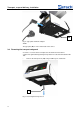
Fig. 8: Mounting the hopper support rod
• Screw the hopper support rod (G) into the threaded hole (Gb) on the
housing.
Pos: 6.10 /00005 Ü berschriften/ 1.1 Überschrifte n/1.1 Überschrift en BDA/11 Trich terhalterung aufsetzen @ 4\mod_13324029 08588_9.doc @ 27410 @ 2 @ 1
3.12 Mounting the hopper support
Pos: 6.11 /00010 Bedienungsa nleitungen Kapitels ammlungen/DR 100_2012/00 06 DR100_201 2 Transport, Lie ferumfang und Au fstellen/DR 100 Modul Tri chterhalterung a ufsetzen @ 4\ mod_133240206 3851_9.doc @ 27327 @ @ 1
G
Gb
C
F