
User guide


Transport, scope of delivery, installation
14
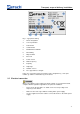
Fig. 5: Mount the vibrating chute support
• Insert the countersunk screws (Fs) into the drill holes (Fb/Fc) of the support.
• First tighten the screw (Fc) using a Phillips screwdriver.
• Then screw the screw (Fb) tight.
NOTE
No sufficient transmission of the vibrations will take place without a strong
connection between vibrating chute and bolt (Fa). The feed cannot be controlled.
• Check that the screws are in the correct position.
Pos: 6.6 /00005 Üb erschriften/1.1 Ü berschriften/ 1.1 Überschrifte n BDA/11 Schüt telrinne einsetz en @ 4\ mod_1332402832 273_9.doc @ 27394 @ 2 @ 1
3.10 Inserting the vibrating chute
Pos: 6.7 /00010 B edienungsanlei tungen Kapitelsa mmlungen/DR1 00_2012/000 6 DR100_2012 Tr ansport, Lief erumfang und A ufstellen/DR1 00 Modul Sch üttelrinne einsetzt en @ 4\mod _1332402060 712_9.doc @ 2731 8 @ @ 1
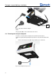
• Clamp the back edge (Cr) of the vibrating chute under the lugs (Fk) of the
holding fixture (F).
Fig. 6: Inserting the vibrating chute
• Press the vibrating chute (C) into the holding fixure (F) until it locks in place.
Fk
Cr
F
Fb
Fs
Fn
Fn
Fa
Fc