
User Manual

Transport, scope of delivery, installation
22
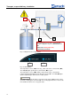
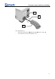
Fig. 11: Diagram of the cooling system
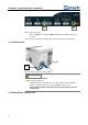
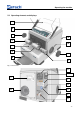
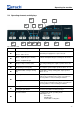
Fig. 12: LED displays
The temperature sensor (TSD) in the LN
2
outlet controls the solenoid valve (MV).
The LED (B1) lights up when the solenoid valve (MV) is open.
The temperature sensor (TSM), which is downstream of the solenoid valve,
registers whether liquid nitrogen is flowing into the CryoMill. The LED (B2) lights
up when liquid nitrogen flows into the cooling system.
CAUTION
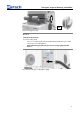
The device must not be moved in a cryogenic state and no additional forces may
act on the cooling agent connection (N). The cooling agent inlet hose must not be
moved while the device is in a cryogenic state.
Pos: 5.34 /00 010 Bedienu ngsanleitungen K apitelsammlunge n/CryoMill II/0 006 Transport, Li eferumfang un d Aufstellen /00 13 CryoMill II Modul Kühls ystem @ 5\mo d_13445111103 12_9.doc @ 3 3952 @ @ 1
The maximum pressure in the external liquid
nitrogen supply line may be a maximum of 1.5
bar.
The use of a safety valve (SV)
is absolutely essential!
B1 (MV)
B2 (TSM)
TSD
TSM
MV
SV