® Retro Classic Owner's & Installation Guide RC-900C AM I FM Radio wi Front Aux input and Infinimount Shaft/Bracket System © Copyright 2010 Retro Manufacturing, LLC No text, illustrations, or format of this manual in printed or electronic form may be copied without written permission from Retro Manufacturing, LLC or any of its subsidiaries. All Rights Reserved. Retro Manufacturing 5785 Waco Street Chino, California 91710 Phone: 909·364·1372 Fax: 909·364·8670 www.retrosoundusa.com Version 2.
• Thank you for your purchase of our Retro Classic Radio! We hope it will provide you with years of enjoyment.
•• • • Page Number Welcome, Warning & Precautions Table of Contents Installation & Use Warnings Location of Controls, Remote, Connectors, etc What's in the Box Preparing to Install Your Unit. Retro Classic Specifications & Dimensions Using Your Unit Setting the Clock Turning the Unit On/Off Volume Adjustment Selecting Your Listening Source Adjusting the Sound Properties Special Modes of Operation/Sub Menu About RDS/ Using RDS functions Selected Source Mode: Radio Selected Source Mode: Auxiliary Input.
Observe the following warnings when using this unit. OThe driver should neither watch the display nor operate the system while driving. Watching the display or operating the system will distract the driver from driving safely and can cause accidents. Always stop the vehicle in a safe location and use the parking brake before watching the display or operating the system. OUse the proper power supply. This product is designed for operation with a negative grounded 12 V DC battery system.
4. Please review this section for quick reference, as it contains information on the location of controls and basic operations. For sBecific d,rWi1s 0~~~7~~~:J&~{i~g;li~g!;.gl*~.~*r~t*r}g.m~table of contents. O POWER on/off: Press the left center knob to turn the unit on. Press and hold the left center knob for 2 seconds to turn the unit off. Turning the center left shaft controls the volume attenuation up and down. Note: Volume range is 0 - 40(Min/Max).
Please review this section for quick reference, as it contains information on the location of controls and basic operations. For specific details~~~~~~~ri~j~~i~i~~i~tn~J~j~tr*nmj~~~,~~~.JQ.~~abl~of contents. ~ T/F Button: Use this button to view the clock, and toggle through various modes. Press and hold to set the clock in conjunction with the left control shaft. ~ MODE Function: Press this button to switch between all modes of operation, Radio/AUX-In 1.
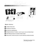
REAR View of Retro Classic RC-900C Internal Amplifier Heatsink Threaded mount for metal backstrap (included) used for rear support of main b o d y ' · · · · · External Antenna Input 4 RCA outputs for adding external amplification Female ISO wire harness connector w/1 male power/ground harness & 1 male speaker lead harness
k- )~~~~J~::~ :,:,,;.
8, ,------------------------------, : PLEASE NOTE THAT THIS UNIT REQUIRES +12V : I TO BOTH THE RED & YELLOW WIRES, I OTHERWISE THE UNIT WILL NOT OPERATE. I I : CALL US OR EMAIL US IF YOU HAVE : I QUESTIONS! I ,------------------------------, Familiarize yourself with the Retro Classic wiring harness (Note: There are 2 plug connectors: Plug "A" which contain power/ground connections & "8" which contains the speaker leads) Retro Classic RC-900C Frequency Range: FM 87.5-107.
Find the Infinimount shafts & brackets (2 of each enclosed) X2 Assemble the Retro Classic unit's Infinimount bracket and shaft system using the supplied screws and shaft nuts. Due to the flexible installation variations this system offers, in order to match the Infinimount shaft & bracket system to the proper shaft width of your vehicle, simply measure the distance between your existing shaft holes center to center.
10. • ..... If Prepare to set up your vehicle-specific kit (Optional 67-72 GM Truck bezel shown as an installation example) Once shafts are lined up to the shaft openings on the vehicle-specific faceplate adapter, use a nut and washer to hold the faceplate in place on the shafts so the Retro Classic's face is flush with the opening of the faceplate (see photos below). NOTE: Modifying or cutting the radio's brackets will not void your warranty, this is what our radio is designed for.
11, • • Below, The final result!: 67-72 GM Truck bezel shown installed in the vehicle's dash, note that the radio face is flush with the bezel in the dash for a professional looking installation. Getting the unit to fit perfectly into your dash is probably the most difficult portion of the install. Patience and persistence is the key. If you still have problems, please send us an email at~lJ.P.P!.)Jt@r~t[Q_~_QlJlJ(;!_lJ§~.<::Qmor give us a call at: 909-364-1372.
• 41 The Retrosound Model One is available with an optional set of metal knobs and a faceplate (for the front of the dash) or bezel (mounts from behind the dash) that fits around the control face of your Model One/Apache or Retro Classic radio(s). Please consult us at support@retrosoundusa.com regarding a universal or vehicle specific faceplate/bezel & knob kit for your car. Below is a Retro Model One shown with an optional 67:-68 Camaro faceplate & Chrome Metal k n o b s . / ' ) " "I .$~«:>~;.
NOTE: The following installation option is for advanced knowledgeable custom installation specialists. The Retro Classic control face is removable to allow for unique angled installations, canted angles, upside-down mounting and other unique configurations limited only to your installation skills. Below is a photo illustrating what the unit looks like with the control face removed, connected by a ribbon cable from the body of the main unit to the radio's control face. (There is about 4.
14. Metal Knob Install Guide Sometimes the Retrosound Shafts need to be adjusted to allow you to mount our metal knobs to the shafts. Once your radio is installed follow the steps below to ensure a proper knob fit. 04 I • 2. For the rear-knob, simply insert a biade screwdriver diagonaiiy to slightly spread apart the secondary back-knob position to allow the rear knob to fit snugly. For the front-knob, use a pair of needle nose pliers and GENTLY crimp the front-knob prongs closer together.
15, Tuner Section Specs FM Tuning Range (Eu & US Tuning Capable) wi ROS Antenna Terminal Usable Sensitivity Selectivity Signal to noise Ratio Harmonic Distortion @ 1 kHz Separation Frequency Response 87.5-107.9MHz Extemal Antenna Connector 12.5 dBf 75 dB @ 400kHz 62 dB (Stereo), 67 dB (Mono) 0.8% (stereo), 0.
16. Setting the Clock: Press the TtF Button on the face of the unit when the unit is turned on. Press and hold the T1F button. When the clock is seen on-screen blinking, use the left shaft center knob, and turn knob right or left to adjust hours (note: AM & PM is adjusted by changing hours). Press the left shaft center knob to select minutes, then turn left or right to adjust. Press TtF button to store the clock settings. (Note: When EU tuning mode selected, militaryt24 hour time mode will be activated).
.A 1 -7 . Adjusting the Sound Properties: The Retro Classic radio has many sound adjustment modes to help you tailor the radio to your preference. To access these modes of adjustment, press the left knob (SEL) in and turn the knob to the right or left to adjust. Then press SEL again to cycle through the choices. When you have completed your adjustments, simply stop adjusting the mode and it will revert to your current setting.
18. To Activate the LOUDNESS function from the Sub Menu, press the center right shaft "SEL" button and hold it for 2 seconds. Then turn the shaft control right or left to toggle the LOUD function ON or OFF. This function boosts bass & trebie at iow iistening voiume and should be turned off at higher volumes. You will know this function is active when you see "LOU" lit up on your display.
SUB-MENU FUNCTION: STEREO/MONO When listening to the AM/ FM tuner, you can access the stereo/mono Sub Menu system. Press and hold the SEL (right center shaft knob). Repeatedly press the center shaft to scroll through the sub menu and turn the knob to the right to select between Stereo/Mono operation. Selecting between these functions can aid in listening to weak FM radio stations that keep switching between Stereo & Mono modes.
WHAT IS RD5? flJJRo'!1~5. RDS stands for Radio Data System. RDS tuners can automatically tune in stations according to the style of music (or talk) they broadcast. Some RDS tuners can even break in with traffic alerts or emergency broadcasts. RDS enables your receiver to display text messages (usually call letters and format info) that many FM stations include on a subcarrier signal within their normal broadcast signal.
• • How to use the PlY function when in the AREA EUR tuner mode RDS has a function called PTY (Program Type). This coding of up to 31 pre defined program types allow you to find similar programming by genre. When the tuner searches for this desired programming type, the tuner will study all strong FM stations to see what programming type they are broadcasting. If the programming type is found, the radio will select it. To use this function, press and hold BAND button for 2 seconds.
22. Selected Source: Radio Once you've selected the radio function, you can start storing your presets or tuning to your preferred station. Press "BAND" to select FM1,2,3 or AM1,2 - - - - - . for a total of 30 Presets To save a preset, tune to the station using the right shaft knob, then choose the preset number you wish to assign to that station. Press and hold the button. Listen for a confirming beep, and now you have saved that preset.
23, LIMITED WARRANTY If your product does not work properly because of defects in materials and workmanship RetroSound a division of Retro Manufacturing, LLC (collectively referred to as "the warrantor") will, for the length of the period indicated in the chart below, which starts with the date of original purchase ("warranty period"), at its option either (a) repair your product with new or refurbished parts, or (b) replace it with a new or refurbished product.
® Retro Classic Owner's & Installation Guide RC-900C AM I FM Radio wi Front Aux input and Infinimount Shaft/Bracket System © Copyright 2010 Retro Manufacturing, LLC No text, illustrations, or format of this manual in printed or electronic form may be copied without written permission from Retro Manufacturing, LLC or any of its subsidiaries. All Rights Reserved. Note: The information enclosed in this installation guide is to be used as merely an outline to assist you during the process of installation.