
Instructions / Assembly


8
ALIGN
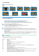
STEP 1.2. Align Screen Cartridge Header (A1) and Screen Pull Bar
(A2) and Cut at your pre-measured “Width” inches mark.
1.2.1. Ensure that the Screen Cartridge Header (A1 ) and Screen Pull Bar
(A2) are aligned so they can be cut evenly at the same time.so as to be able
to cut them both evenly at the same time. (See Figure: 1.2A)
1.2.2. On the Screen Cartridge Header (A1) you will find a Glued Measuring
Tape Template (N) pre-adhered to the Screen Cartridge Header (A1).
(See Figure:1.2B) MARK the Measuring Tape Template on the Screen
Cartridge Header (A1) at “W inches” (the window's Head Jamb opening
WIDTH measurement determined and recorded in Box W in Step 1.1.
above).
1.2.3. CUT the Screen Cartridge Header (A1) and Screen Pull Bar (A2)
contemporaneously AT the “W inches” width you determined as the Head
Jamb WIDTH in Step 1.1.
CUT at “W” ON the Measuring Tape Template (N) glued onto the Screen
Cartridge Header (A1).
DO NOT use YOUR household measuring tape to determine where
to cut on the Screen Cartridge Header A(A1/A2). ONLY use YOUR
household measuring tape to MEASURE the Head Jamb in Step 1.1. above
NOT to cut here in Step 1.2.
Use the numbers on Glued Measuring Tape Template (N) to identify where
to cut the Screen Cartridge Header A(A1/A2)
Figure 1.2A
BOX W
“W”= where to cut
Figure 1.2B
STEP 1.3. Completing Preparation of Screen Cartridge Header - Install
Permanent End Cap - Add Finishing Hardware Components
1.3.1. Remove or file away any burrs and scrap resulting from the
cutting.
1.3.2. If you have cut the Left End of the Screen Cartridge Header (A1) the
temporary end cap will have fallen off along with the portion of the Screen
Cartridge Header (A1) that was cut off, if the Screen Cartridge Header was
the correct size and you did NOT have to cut, then please REMOVE the
TEMPORARY Left End Cap at this time.
To maintain the alignment of the mechanisms IN TRANSIT, the temporary
end cap is placed on the Left end of the Screen Cartridge Header A (A1/
A2) at the Factory. After you have removed the TEMPORARY Left End Cap
please replace it with part (E) so as to minimize the displacement of the
precisely torsioned spring inside Screen Cartridge Header A(A1/A2) as you
complete your assembly and installation.
1.3.3. Insert one of the Handles (B) in the appropriate slit channel opening
in the Screen Cartridge Pull Bar (A2) (See Figure: 1.3.3.) and slide Handle
(B) to the right until Handle (B) is positioned where it will be comfortable for
you to use (when you pull the Pull Bar (A2), down or up). Note the handle
spacing will REMAIN adjustable throughout the life of the product so note
that you will be ABLE to change the handle spacing at whim.
1.3.4. Insert the Pull Cord (C ) in the appropriate slit channel opening in the
Screen Cartridge Pull Bar (A2) and slide Pull Cord (C ) to the center of the
Screen Cartridge Pull Bar (A2). (See Figure 1.3.4.)
1.3.5. Insert the second Handle (B) into the appropriate slit channel opening
in the Screen Cartridge Pull Bar (A2) and slide until second Handle (B) is
positioned left of center to where it will be comfortable for you to use.
I
M
P
O
R
T
A
N
T
I
M
P
O
R
T
A
N
T
!
Figure 1.3.4
Figure 1.3.3
Figure 1.3.6C
Figure 1.3.6A Figure 1.3.6B
MARK
CUT
A1&A2
N
Glued Measuring Tape Template