
Installation Guide

9
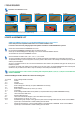
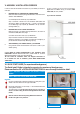
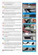
1.3.6. Take the 2 x (D) (Pull Bar End Caps) parts which are still attached by
plastic to distinguish the right and left parts.
Push the Left Pull Bar End Cap (D) into the end of the Pull Bar (A2). (See
Figures: 1.3.6A, 1.3.6B and 1.3.6C)
The Installation Video clearly shows how to separate the 2 Pull Bar End
Caps (D), cleanly. You can view it in Section 1 of the Installation Video:
MEASURING AND PREPARING THE MOSQUITO SCREEN HEADER at
url: https://www.youtube.com/watch?v=3v0fAe30kJQ&feature=youtu.be
1.3.7. Push the second remaining Right Pull Bar End Cap (D) into the other
end of the Pull Bar (A2) (See Figure 1.3.7A)
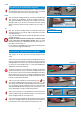
The Pull Bar End Caps (D) once inserted should stay on the Pull Bar (A2)
If the End Caps should slip off the Pull Bar you can secure them onto the
Pull Bar ends by using the pliers to pinch the Pull Bar channel so as to lightly
crush the channel against the Pull Bar End Cap (D)
(See Figures 1.3.7B and 1.3.7C Alternatively you can carefully insert a
small rectangle of scotch tape or a dab of glue to adhere the Pull Bar End
Cap (D) to the Pull Bar (A1) ends.
Any small scratch caused by the pinching will not show as ultimately the Pull
Bar End Cap portion will be hidden by the Side Insect Screen Track it will be
inserted into. (See Figures1.3.7B and 1.3.7D)
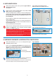
1.3.8. Pick up the Screen Cartridge LEFT End Cap (E) and the Brake
Mechanism (F) in the hardware component box.
Insert the Brake Mechanism (F) onto the Screen Cartridge LEFT End Cap
(E) by inserting the Brake Mechanism (F) on the protruding round post in
the Screen Cartridge LEFT End Cap (E).
Rotate the Brake Mechanism (F) onto the post in the Screen Cartridge
LEFT End Cap (E) while applying a slight push pressure on the Brake
Mechanism's (F) spring. (See Figure 1.3.8A)
Insert the Screen Cartridge LEFT End Cap/Brake Mechanism (E/F) unit you
have created, into the slotted cavity of the Screen Cartridge Header (A1).
(See Figure 1.3.8B)
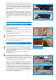
1.3.9. Secure the Cartridge LEFT End cap/Brake Mechanism (E/F)unit
to the Screen Cartridge Header (A1) by screwing the included Screen
Cartridge Header Screw (G) into the Screen Cartridge Header (A1). (See
Figure 1.3.9A)
If you have difficulty pushing the End Cap into the channel ensure that the
End Cap insertion channel clip is clear of any plastic debris with a cutter
blade. This will enable the End Cap to ease into the Screen Cartridge
Header's channel. When you are finished the Left End Cap should appear
as in Figure 1.3.9B.
1.3.10. Get Cone Spring (H) and Screen Cartridge RIGHT End Cap Add-On
(I). Position LARGE side of Cone Spring (H) to face the Screen Cartridge
Header (A1) AND with Cone Spring's (H) small side against Screen Cartridge
RIGHT End Cap Add-On (I). (See Figure 1.3.10A and 1.3.10B)
There is a round protruding plastic post in Screen Cartridge RIGHT End
Cap Add-on (I) insert the center of the small side of the Cone Spring (H)
onto that post. (See Figure 1.3.10A and 1.3.10B)
Please NOTE that the Cone Spring (H) part is a LOOSE part it is NOT
meant to secure firmly onto the post.
Figure 1.3.9A
Figure 1.3.8A
Figure 1.3.8B
Figure 1.3.7C Figure 1.3.7D
Figure 1.3.7A
Figure 1.3.7B
Figure 1.3.10A
Figure 1.3.10B
Figure 1.3.9B
I
M
P
O
R
T
A
N
T
I
M
P
O
R
T
A
N
T
!