
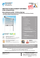
Installation Guide

6
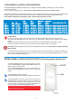
If you DO NOT have the 2 inches (5.08 cm) of space in your HEAD JAMB you need to install the Screen Cartridge Header A(A1/A2), you can still
install the retractable insect screen, however you will need an alternate installation accessory kit, such as our Frontal Installation accessory kit by
contacting us at; customerservice@retractablebugscreen.com or call us at 1-407-450-5134
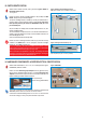
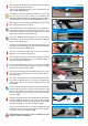
V.3. CAREFULLY REMOVE packaging from your RETRACTABLEBugScreen TM, so as to be able to access all kit parts and
components. Please refer to our 10 minute installation video to see how to best remove all packaging.
https://www.youtube.com/watch?v=3v0fAe30kJQ&feature=youtu.be
Ensure you have all parts and hardware components identified in Section III and Section IV of this guide.
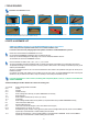
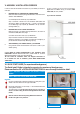
V.4. It is important to understand which side is the RIGHT side of the HEADER, so as to correctly follow the installation instructions.
To clarify which side of the HEADER is considered RIGHT and which is considered LEFT in the instructions,
please PLACE the HEADER Part A FACE UP as illustrated in Figure: PARTS, of RetractableBugScreen TM shown in section III of
this Instruction Guide.
That means that the curved frontal part of Screen Cartridge Header (A) will be facing you the do-it-yourselfer or installer.
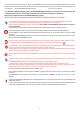
V.5. An Existing Permanent End Cap (O) has been Factory installed on the RIGHT side of the Screen Cartridge Header (A1)
DO NOT REMOVE or tamper with the aforementioned permanent RIGHT End Cap (O). (On the RIGHT side of the Screen Cartridge
Header (A1)
The factory installed PERMANENT End Cap (O) is linked to the retractable screen mechanism and precisely torsioned so it is important
NOT to tamper with the PERMANENT End Cap.
DO NOT unscrew or tamper with either of the two Phillips head screws on the RIGHT side of the Screen Cartridge HEADER (A1) on the
aforementioned Factory installed PERMANENT End Cap (O). This is what a Phillips Head screw tip looks like:
It is important NOT to tamper with the Permanent End Cap or the Phillips head screws on the RIGHT side of Screen Cartridge Header as
the screen mechanism is precisely machine torsioned within the Screen Cartridge Header (A1).
Tampering with the aforementioned Permanent End Cap on Right side of Header (A) or tampering with Phillips Head screws on the RIGHT
side of the Screen Cartridge HEADER (A1) will BREAK the unit.
The UNIT will NOT function if the Phillips Head Screws on the RIGHT side of the Screen Cartridge Header are unscrewed or tampered
with!
The RIGHT side of the Screen Cartridge Header (A1) can be identified as the RIGHT side by the differentiation that the RIGHT SIDE
has:
i) A PERMANENT END CAP with TWO Phillips Screws. Right side is only side with 2 Phillips screws
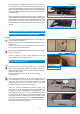
ii) The Right Side of Header A(A1/A2) does NOT have the Glued Measuring Tape Reference Guide (N) adhered to it's side.
Only the LEFT side of the Screen Cartridge Header (A1) has a reference measuring tape adhered to it as only the LEFT side of the Screen
Cartridge Header (A1) will be cut and thus it is the only side that needs a reference measuring tape.
Please note the right side of the header is the side that will NOT be cut.
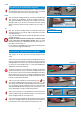
V.6. To maintain the alignment of the mechanisms IN TRANSIT, a temporary end cap is placed on the LEFT end of the Screen Cartridge
Header (A1).
The TEMPORARY Left End Cap will be removed by you and replaced with HARDWARE component (E) in Step 1.3.2.. of the
assembly.
The factory installed End Caps MAY have become slightly displaced in transit. If this occurred firmly push the factory installed End Caps
FIRMLY back into place.
In order to protect the functionality of the retractable screen mechanism please ensure the factory installed End Caps are securely attached
to the Screen Cartridge Header (A1) before you start to assemble the product and BEFORE pulling on the Pull Bar (A2).
I
M
P
O
R
T
A
N
T
I
M
P
O
R
T
A
N
T
!
I
M
P
O
R
T
A
N
T
I
M
P
O
R
T
A
N
T
!