
Installation Guide

3
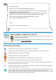
I. TOOLS REQUIRED
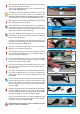
ASSEMBLE RECOMMENDED TOOLS
1. Drill 2. Metal File* 3. Drill Bits** 4. Pencil 5. Pliers
6. Measuring Tape 7. Handsaw 8. Cutter 9. Screwdriver (Phillips)
* NOTE:Metal File is optional yet handy for adjustments required by disparities caused by irregular or not level window sills or to file away metal irregularities or burrs.
** Use 5/32 in.(3.97mm) (drill bit for metal) Use 7/32 in.(5.56 mm) (drill bit for masonry)
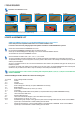
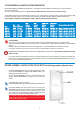
II. PARTS & HARDWARE LIST
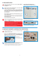
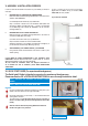
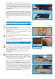
CAREFULLY REMOVE packaging from your RETRACTABLEBugScreen TM, so as to be able to
access all kit parts and components. Please refer to our 10 minute installation video
to see how to best remove all packaging. https://www.youtube.com/watch?v=3v0fAe30kJQ&feature=youtu.be
Please ensure that all PARTS and HARDWARE are in the kit.
Use this PARTS & HARDWARE OVERVIEW to help you identify the kit parts.
Please open the RetractableBugScreen TM package - LAY OUT ALL PARTS INCLUDED IN THIS KIT.
The small white box contains the HARDWARE for this kit.
Parts and Hardware are listed as A, B, C, D, E , F, G, H, I, J, K, L and M.
The Parts and Hardware are listed in alphabetical order, to facilitate the assembly and installation of your Retractable Insect Screen.
The alphabetical ordering of parts and components is used, to provide an idea of when in the assembly and installation process you will
need the parts and hardware.
As much as is possible the order of use of the Parts and Hardware has been related to the alphabetical order given the relevant part or
hardware component.
For example, Part A1&A2 (The Header and the Pull Bar) are the first piece used in your RetractableBugScreen TM kit assembly and
installation so they are listed as Part A1&A2, as they are used early in the assembly and installation process.
Large parts A (A1/A2) and J come in main box, remaining small components (B,C, D, E, F, G, H, I, K, L, M) are in a small white box
labelled “HARDWARE.
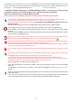
Your RetractableBugScreen TM for Windows Kit contains the following parts:
1 x A (A1/A2) Screen Cartridge Header and Pull Bar
2 x B Handles
1 x C Pull Cord
2 x D Pull Bar End Caps
1 x E Screen Cartridge LEFT End Cap (To replace TEMPORARY Left End Cap)
1 x F Brake Mechanism
1 x G Screen Cassette Header Screw (4 x 25 mm) (4 x .984 in.)
1 x H Cone Spring
1 x I Screen Cartridge Header RIGHT End Cap Add-On (To be placed ONTO factory installed PERMANENT End Cap)
2 x J Lateral Insect Screen Side Tracks
1 x K Reference Measuring Tape
2 x L Lateral Track Insect Screen Stoppers (a LEFT and a RIGHT screen stopper)
8 x M Screws & Anchors (4 x 35 mm ) (4 x 1.37 in.)
1 x N Glued Measuring Tape Template- Factory glued to top side of Screen Cartridge Header A(A1/A2)- Please note this is NOT a
separate part, it is identified here to facilitate following Instruction Guide.
1 x O Existing Permanent End Cap - Factory Installed and NOT to be tampered with or REMOVED - Please note this is NOT a
separate part, it is identified here to facilitate following Instruction Guide.