
Installation Guide

18
ALIGN
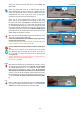
STEP 2: MEASURING AND PREPARING the LATERAL SIDE TRACKS
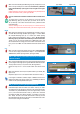
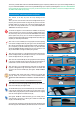
STEP 2.1. Measure the HEIGHT of the INSIDE SIDE JAMB
Measure the INSIDE SIDE JAMB height (height of the window opening) as
pictured in Figure 2.1A and 2.1B.
Measure both the LEFT and the RIGHT window opening height as not all
Sills will be level.
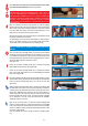
In order to be precise in your cutting we recommend you note both
measurements and ensure they are equal.
Write the window's INSIDE JAMB HEIGHTmeasurement in the box H to the
right for easy reference.
In Step 2.1.4. below you use this “H” inches measurement for reference
when cutting the Lateral Insect Screen Tracks (J)
STEP 2.1. TIPS
If the Right and Left heights are not equal adjust for that by cutting the
Lateral Screen Tracks (J) separately at the different
“H” inches /Height measurements, instead of together as recommended for
sills that are level
in which case the two Lateral Screen Tracks (J) should be cut
together.
For very minor differences in the heights of the window jambs, the metal file
can be used to slightly file
down the metal to the appropriate height.
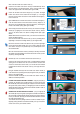
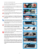
STEP 2.2. Align Lateral Insect Screen Side Tracks (J) and Cut at your
pre-measured “Height” inches mark.
2.2.1. Take the two Lateral Insect Screen Side Tracks (J), held together
by their protective packaging. REMOVE the packaging. Separate the
Lateral Insect Screen Side Tracks (J) and align them evenly, keeping the
brushweatherstrips centered.
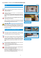
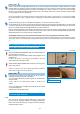
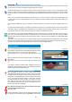
STEP 1.3. TIPS
Please note that Screen Cartridge Right End Cap Add -On (I) and Cone Spring (H) assembly will be LOOSELY attached to the Screen
Cartridge Header (A1) despite your firm push, the Right End Cap Add-on (I) will remain loosely connected to the Screen Cartridge Header
(A1) because it is intentionally designed to be loose so as to provide give and lee-way to allow you to adapt your Screen Cartridge
Header (A1) to your window's Head Jamb width opening; later on in the assembly process, when you insert The Screen Cartridge Header
(A1) into the upper recess of the window jamb.
Do not be concerned if the Cone Spring (H) falls off the end or does not seem secure or seems loose to you, it is meant to be flexible
and provide expansion or give, to fulfill its function of providing give as the Screen Cartridge Header (A) is inserted into the window
jamb.
The loose Cone Spring (H) may cause the Right End Cap Add-on (I) to be so loose that End Cap falls off.
If you would like you can use a piece of clear scotch tape to keep the End Cap (I) secured to Screen Cartridge Header A1, by taping a piece
of scotch or masking tape on the outside back side of the Screen Cartridge Header and folding it across the End Cap (I) so as force End
Cap (I) to stay in place until Screen Cartridge Header (A) is installed in Head Jamb.
Place the temporary masking or scotch tape where you will be able to remove it when you insert the assembled Screen Cartridge Header
A(A1/A2) into the window's Head Jamb. Or place the temporary scotch tape on same face of Screen Cartridge Header A1 where factory
installed measuring tape is, as this face of Screen Cartridge Header
GOOD WORK! At this point you have completed the assembly of the Screen Cartridge Header and Pull Bar (A1/A2).
Put the Screen Header Cartridge (A) aside for now, and measure and prepare the Lateral Side Tracks (J) as per instructions in Step 2
below, then in Step 3 you will join the Screen Cartridge Header A (A1/A2) you have just completed with your prepared Lateral Side Tracks
(J).
Figure 2.1A
Figure 2.1B
BOX H
H =
MEASURE