
Installation Guide

17
inserted into. (See Figures1.3.7B and 1.3.7D)
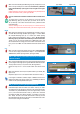
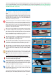
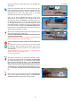
1.3.8. Pick up the Screen Cartridge LEFT End Cap (E) and the Brake
Mechanism (F) in the hardware component box.
Insert the Brake Mechanism (F) onto the Screen Cartridge LEFT End Cap
(E) by inserting the Brake Mechanism (F) on the protruding round post in
the Screen Cartridge LEFT End Cap (E).
Rotate the Brake Mechanism (F) onto the post in the Screen Cartridge
LEFT End Cap (E) while applying a slight push pressure on the Brake
Mechanism's (F) spring. (See Figure 1.3.8A)
Insert the Screen Cartridge LEFT End Cap/Brake Mechanism (E/F) unit you
have created, into the slotted cavity of the Screen Cartridge Header (A1).
(See Figure 1.3.8B)
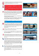
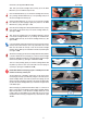
1.3.9. Secure the Cartridge LEFT End cap/Brake Mechanism (E/F)unit
to the Screen Cartridge Header (A1) by screwing the included Screen
Cartridge Header Screw (G) into the Screen Cartridge Header (A1). (See
Figure 1.3.9A)
If you have difficulty pushing the End Cap into the channel ensure that the
End Cap insertion channel clip is clear of any plastic debris with a cutter
blade. This will enable the End Cap to ease into the Screen Cartridge
Header's channel. When you are finished the Left End Cap should appear
as in Figure 1.3.9B.
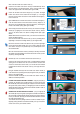
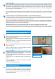
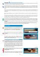
1.3.10. Get Cone Spring (H) and Screen Cartridge RIGHT End Cap Add-On
(I) Position LARGE side of Cone Spring (H) to face the Screen Cartridge
Header (A1) AND with Cone Spring's (H) small side against Screen Cartridge
RIGHT End Cap Add-On (I). (See Figure 1.3.10A and 1.3.10B)
There is a round protruding plastic post in Screen Cartridge RIGHT End
Cap Add-on (I) insert the center of the small side of the Cone Spring (H)
onto that post. (See Figure 1.3.10A and 1.3.10B)
Please NOTE that the Cone Spring (H) part is a LOOSE part it is NOT
meant to secure firmly onto the post.
The Cone Spring (H) is intended to remain loose, as the function of the
Cone Spring (H) is merely to provide leeway and give for the End Cap of the
Screen Cartridge Header, as the End Cap and the Cone Spring (H) work
together to provide a flexible give and take for the Screen Cartridge Header
(A1) when the Screen Cartridge Header (A1) is inserted in the upper recess
of the Window jamb.
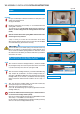
With Cone Spring (H) positioned as described in Step 1.3.10 and seen in
Figure 1.3.10C, slip the Cone Spring (H) and the Screen Cartridge Header's
Right End Cap Add-on (I) onto the Screen Cartridge Header (A1). Push
in firmly. When you finish adding on the RIGHT End Cap to the factory
installed Permanent End Cap your Right End Cap should look like Figure
1.3.10D
Figure 1.3.8A
Figure 1.3.9A
Figure 1.3.8B
Figure 1.3.9B
I
M
P
O
R
T
A
N
T
I
M
P
O
R
T
A
N
T
!
Figure 1.3.10A
Figure 1.3.10B
Figure 1.3.10C
Figure 1.3.10D