
Installation Guide

16
STEP 1.3. Completing Preparation of Screen Cartridge Header - Install
Permanent End Cap - Add Finishing Hardware Components
1.3.1. Remove or file away any burrs and scrap resulting from the
cutting.
1.3.2. If you have cut the Left End of the Screen Cartridge Header (A1) the
temporary end cap will have fallen off along with the portion of the Screen
Cartridge Header (A1) that was cut off, if the Screen Cartridge Header was
the correct size and you did NOT have to cut, then please REMOVE the
TEMPORARY Left End Cap at this time.
To maintain the alignment of the mechanisms IN TRANSIT, the temporary
end cap is placed on the Left end of the Screen Cartridge Header A (A1/
A2) at the Factory. After you have removed the TEMPORARY Left End Cap
please replace it with part (E) so as to minimize the displacement of the
precisely torsioned spring inside Screen Cartridge Header A(A1/A2) as you
complete your assembly and installation.
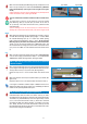
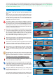
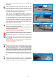
1.3.3. Insert one of the Handles (B) in the appropriate slit channel opening
in the Screen Cartridge Pull Bar (A2) (See Figure: 1.3.3.) and slide Handle
(B) to the right until Handle (B) is positioned where it will be comfortable for
you to use (when you pull the Pull Bar (A2), down or up). Note the handle
spacing will REMAIN adjustable throughout the life of the product so note
that you will be ABLE to change the handle spacing at whim.
1.3.4. Insert the Pull Cord (C ) in the appropriate slit channel opening in the
Screen Cartridge Pull Bar (A2) and slide Pull Cord (C) to the center of the
Screen Cartridge Pull Bar (A2). (See Figure 1.3.4.)
1.3.5. Insert the second Handle (B) into the appropriate slit channel opening
in the Screen Cartridge Pull Bar (A2) and slide until second Handle (B) is
positioned left of center to where it will be comfortable for you to use.
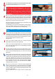
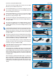
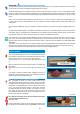
1.3.6. Take the 2 x (D) (Pull Bar End Caps) parts which are still attached
by plastic to distinguish the right and left parts Push the Left Pull Bar End
Cap (D) into the end of the Pull Bar (A2). (See Figures: 1.3.6A, 1.3.6B and
1.3.6C)
The Installation Video clearly shows how to separate the 2 Pull Bar End
Caps (D), cleanly. You can view it in Section 1 of the Installation Video:
MEASURING AND PREPARING THE MOSQUITO SCREEN HEADER at
url:
https://www.youtube.com/watch?v=3v0fAe30kJQ&feature=youtu.be
1.3.7. Push the second remaining Right Pull Bar End Cap (D) into the other
end of the Pull Bar (A2) (See Figure 1.3.7A)
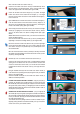
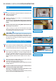
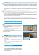
The Pull Bar End Caps (D) once inserted should stay on the Pull Bar (A2)
If the End Caps should slip off the Pull Bar you can secure them onto the
Pull Bar ends by using the pliers to pinch the Pull Bar channel so as to lightly
crush the channel against the Pull Bar End Cap (D)
(See Figures 1.3.7B and 1.3.7C Alternatively you can carefully insert a
small rectangle of scotch tape or a dab of glue to adhere the Pull Bar End
Cap (D) to the Pull Bar (A1) ends.
Any small scratch caused by the pinching will not show as ultimately the Pull
Bar End Cap portion will be hidden by the Side Insect Screen Track it will be
I
M
P
O
R
T
A
N
T
I
M
P
O
R
T
A
N
T
!
Figure 1.3.3
Figure 1.3.4
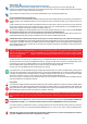
The reason you MUST ONLY USE the included Glued Measuring Tape Template (N) adhered to the top of Screen Cartridge Header (A1)
as your CUTTING REFERENCE, is that the factory Glued Measuring Tape Template (N) was designed to INCLUDE a MEASUREMENT
CALCULATION that makes allowances for the space you will need in the Head Jamb for the WIDTH of the Screen Cartridge Header A(A1/
A2) AND the add-on END caps (E) and (I).
Figure 1.3.7A
Figure 1.3.7B
Figure 1.3.6C
Figure 1.3.6A Figure 1.3.6B
Figure 1.3.7C Figure 1.3.7D