
Installation Guide

12
STEP 3.1. INSTALLING the HEADER and LATERAL TRACKS into
WINDOW
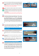
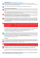
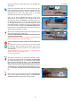
3.1.1. Insert the Screen Cartridge Header (A1) into the top of the window
opening by first inserting the side without the Cone Spring (H) into the top
of the window opening and then pushing the other side into position while
exerting lateral pressure against the Screen Cartridge Header (A1) until the
Screen Cartridge Header (A) is seated into position.
(See Figure 3.1)
Ensure that the Screen Cartridge Header (A1) is correctly and securely
inserted within the wall opening. (See Figure 3.1A)
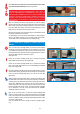
Ensure that The Screen Cartridge Header (A1) is parallell to the window
jamb corner and IN contact with the top of the HEAD JAMB (top of window
beam). (See Figure 3.1B)
Using the included screws (M) affix the Screen Cartridge Header (A1) to the
wall or window opening, by drilling screws (M) through the corresponding
holes in the Screen Cartridge End Caps (E & I) and into the wall. (See
Figure 3.1C)
Drilling the Retractable Insect Screen Screen Tracks into the wall will make
the Retractable Insect Screen more secure and is required for installations
as drilling secures the Retractable Insect Screen firmly making the Insect
Screen safer. Additionally, this securing of the Insect Screen allows for
smoother operation of the screen over time as the insect screeen rises and
lowers in the Side Insect Screen Tracks. This smooth operation facillitated
by firm adherence to the wall it has been drilled into will PREVENT
operational problems in the future.
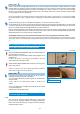
Note: To affix to cement walls or to other wall structures requiring Wall
Anchors, mark hole positions on the wall that correspond to the pre-drilled
holes in the plastic Screen Header End Caps. Move the Screen Cartridge
Header (A1) slightly to enable you drilling corresponding holes with a 15/64
inch (6mm) concrete drill bit.
Insert the included wall anchors, realign the Screen Cartridge Header
(A1).
I
M
P
O
R
T
A
N
T
I
M
P
O
R
T
A
N
T
!
Figure 3.1C
Figure 3.1
Figure 3.1BFigure 3.1A
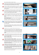
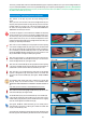
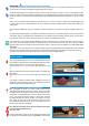
2.4.2. With pliers pinch both ends of the Lateral Insect Screen Tracks
(J) where the brushweatherstrip lies. (See Figure 2.4.2.)
You MUST pinch the small metal channel that holds the
brushweatherstrip, against the brushweatherstrips in such a way as to
secure the brushweatherstrips and PREVENT them from moving. The
brushweatherstrips must NOT move in future, for if they do they will entangle
themselves in the Screen Cartridge Header's mechanism and cause the
mechanism to stop functioning. The pinching in this step is CRITICAL
to the functioning of the mechanism as it will immobilize and secure the
brushweatherstrips.
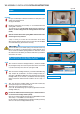
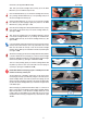
2.4.3. Insert Lateral Insect Screen Track Stoppers (L) inside the apposite
insertion channels found in the Lateral Insect Screen Tracks (J) (See Figure
2.4.3.) Please note you will be placing the Stopper (L) in the LEFT channel
of the LEFT Side Insect Screen Track and the second Stopper (L) in the
Right channel of the RIGHT Side Insect Screen Track.
Note that the pointed tip of the Lateral Insect Screen Track Stoppers should
be inserted tip side first into the channel.
The protruding tip part of the Screen Track Stopper (L) should facing the
interior of the window opening, that is; facing the Lateral Insect Screen
Track or Side Jamb on the opposite side of the window opening.
I
M
P
O
R
T
A
N
T
I
M
P
O
R
T
A
N
T
!
I
M
P
O
R
T
A
N
T
I
M
P
O
R
T
A
N
T
!
Figure 2.4.3
Figure 2.4.2