
Instructions / Assembly

www.retractalight.com
A. GROUND INSTALLATION:
Only Tools Required … Shovel Wire Strippers/Snippers Small Screwdriver
1. Mark or Flag the location where Retract A Light will be placed on your property. We recommend every 10 feet. If the
location chosen is a Deck or Dock please skip down to the Deck/Dock Installation Instructions in section B.
2. Choose a convenient location to mount the Retract A Light controller. The controller can be mounted either inside or
outside the house or building. Be sure to locate the controller within 3 feet of a 110 volt GFCI receptacle. AVOID
USING EXTENSION CORDS.
3. Using the template provided mount the controller. DO NOT PLUG IT IN.
4. Select a path from the controller to the fixtures. This path will be used to route your ¼” air tube and landscape
lighting wire.
5. Using your shovel, dig a narrow trench 2” wide by a minimum of 3” deep to each marked fixture spot.
6. Once your trench is complete dig the holes for the fixtures. They should be approximately 12” deep by 3” wide which
will provide adequate work area.
7. Next lay you’re tubing and wire from the controller through the trench to the last fixture.
8. Place you Retract A Light fixtures next to each hole you have dug.
9. Using a pair of wire strippers, cut the landscape wire at each fixture. The ends after cutting should overlap at least 3”
for the purpose and ease of working with the wire. BE SURE THAT THE FIXTURE WIRE meets the landscape wire
from the controller.
10. With the wire strippers, carefully strip the wire jacket (black casing) back away from the copper strands and expose
them at least 1” back. You will need to do this four times per fixture except for the last fixture which will require two
times.
11. Now twist together one lead from the fixture to one of the wire laid out from the controller. Using the wire nuts
supplied, screw in a clockwise motion the wire nut over the twisted wires until it is snug. Twist one lead to the wire
leading to the fixture and the other lead to the wire leading to the next fixture.
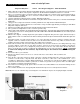
12. Start at the last fixture and connect the tubing this fixture, first. Push the air tube in to the fitting until snug. Using
your wire strippers cut the tube at each fixture locations. Connect the enclosed gray tee fittings to the tube by
pushing the tube into the tee (see diagram A). Then push the tee into the side of the fixture. Do this with all the
fixtures except the last one where you will push the tubing directly on to the side of the fixture. NOTE – if you need
to remove the tubing from the connector, slip the blue ring off the connector first before removing the
tubing.
13. Connect the tube to your controller.
14. Return to the fixtures and use the excess to connect from the tee to the fixture. Trim each time to the
proper length.
15. Once all tube connections have been made, return the controller and attach the wire end to the terminal on the
controller. You will need to strip wire back and attach each wire to either side of the terminal block. Use a
screwdriver to tighten wire connection within terminal block. Next plug your controller in the GFCI receptacle and
rotate timer around clockwise until the system turns on. Make sure you turn on the system to make sure all the lights
are operating correctly before burying the fixtures.
16. If the fixtures are working properly, put the fixtures in their holes and backfill the holes and trench making sure the
fixtures are straight
17. The controller should become silent (pump will shut down when pressure is reached) after 2-5 minutes.
Note: When in use, the controller may occasionally turn on to maintain the air pressure keeping the lights extended.
Diagram A
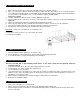
The completed system