
Instruction manual
PerkinElmer Optoelectronics iv
6.5 VERIFYING SLAVE MODE OPERATION................................................................20
7 TARGET SPEED DETERMINATION ...............................................................................21
7.1 TARGET SPEED AND EXPOSURE RELATIONSHIPS.................................................21
7.2 SAMPLE IMAGING SETUP...................................................................................22
8 TROUBLESHOOTING.....................................................................................................23
8.1 TROUBLESHOOTING CHECK LIST .......................................................................23
8.2 RMA (RETURN MATERIAL AUTHORIZATION).....................................................23
8.3 CONTACTING CUSTOMER SUPPORT....................................................................24
APPENDIX A INTERFACE GUIDELINES .......................................................................25
A.1 RS-422 DIGITAL INTERFACE..............................................................................25
A.2 VIDEO RECEIVER...............................................................................................26
List of Figures
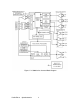
Figure 1 LC3000 Series Camera Block Diagram...................................................................2
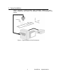
Figure 2 Typical Machine Vision Environment.....................................................................3
Figure 3 Master Mode Timing..............................................................................................6
Figure 4 Slave Mode Timing................................................................................................7
Figure 5 Imaging Geometry Definition.................................................................................9
Figure 6 Camera Front Face Attachment Point Definition...................................................11
Figure 7 LC3000 Series Camera Mounting Hole Location..................................................12
Figure 8 Test Target...........................................................................................................17
Figure 9 Test Target Placement...........................................................................................17
Figure 10 Camera Control DIP switch Location..................................................................18
Figure 11 RS-422 Digital I/O Circuit..................................................................................25
Figure 12 Recommended Video Line Receiver Circuit........................................................26
List of Tables
Table 1 Line Period Limit Definition....................................................................................8
Table 2 Camera Sensor Array Lengths..................................................................................9
Table 3 RS-422 Connector Pin Assignment........................................................................13
Table 4 Camera Operating Mode Selection.........................................................................18
Table 5 Video Gain Selection.............................................................................................18
Table 6 Video Offset Selection...........................................................................................19