
Instruction manual

13 PerkinElmer Optoelectronics
5.5 Interface Cabling
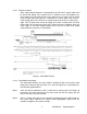
The signal interface cable supports an RS-422 interface to receive the external
LT, LR and MCLK signals and to output the LEN, CLT and CCLK signals.
Additionally the cable connects power to the camera and provides the analog
video output. Contact PerkinElmer for cabling options.
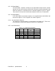
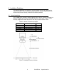
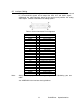
Table 3 RS-422 Connector Pin Assignment
Signal Pin Description
N/C 1 No Connection
N/C 2 No Connection
CCLK+ 3 Camera Clock +
MCLK- 4 Master Clock -
N/C 5 No Connection
N/C 6 No Connection
CLT+ 7 Camera Line Transfer +
LEN- 8 Line Enable -
N/C 9 No Connection
LR+ 10 Line Reset +
N/C 11 No Connection
VIDEO- 12 Analog Video -
POWER+ 13 Input DC Power +
POWER RETURN 14 Input Power Common
MCLK+ 15 Master Clock +
CCLK- 16 Camera Clock -
LT+ 17 External Line Transfer +
LT- 18 External Line Transfer -
CLT- 19 Camera Line Transfer-
LEN+ 20 Line Enable +
N/C 21 No Connection
LR- 22 Line Reset-
N/C 23 No Connection
VIDEO+ 24 Analog Video +
N/C 25 No Connection
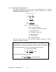
Note: Always observe proper EMI shielding configuration if fabricating your own
cable.
See APPENDIX A for interface circuit guidelines.