Digital Imaging LC3000-Series Camera Instruction Manual I N S T R U C T I O N Imaging M A N U A L PerkinElmer Optoelectronics 2175 Mission College Blvd. Santa Clara, CA 95054 Tel: 408-565-0830 Toll Free: 800-775-OPTO (6786) Fax: 408-565-0703 E-Mail: opto@perkinelmer.com http://www.perkinelmer.com www .perkinelmer .com/opto 055-0458-MAN Rev.
Copyrights, Patents and Trademark Credits PerkinElmer, the PerkinElmer Logo and the stylized P are trademarks of PerkinElmer, Inc. Reticon is a registered trademark of PerkinElmer, Inc. Warranty Seller warrants that the article to be delivered under this order will be free from defects in material and workmanship under normal use and service for a period of one year from date of shipment.
Table of Contents 1 I NTRODUCTION ................................ ................................ ................................ ..............1 1.1 1.2 1.3 1.4 WHAT’ S I N THIS MANUAL ................................ ................................ ...................1 PURPOSE................................ ................................ ................................ ............1 PRODUCTOVERVIEW ................................ ................................ ..........................
6.5 V ERIFYING SLAVE M ODE OPERATION ................................ ................................ 20 7 TARGET SPEED D ETERMINATION ................................ ................................ ...............21 7.1 TARGET SPEED ANDEXPOSURERELATIONSHIPS................................ .................21 7.2 SAMPLE IMAGING SETUP................................ ................................ ...................22 8 TROUBLESHOOTING ................................ ................................
1 Introduction 1.1 What’s In this Manual This manual describes the receiving, unpacking and inspection of your LC3000 series camera. Included is a operational overview that defines the camera operation and the controls provided. Guidance is provided for the installation, setup and initial operation of your LC3000 camera. 1.2 Purpose To provide machine vision system engineers and technicians a definitive guide for integrating LC3000 series cameras into their specific machine vision application. 1.
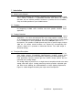
Figure 1 LC3000 Series Camera Block Diagram PerkinElmer Optoelectronics 2
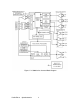
2 Typical Installation Figure 2 illustrates a typical machine vision installation showing the major system components and defines the coordinate system used throughout this manual.
3 Receiving and Inspecting Your Camera 3.1 Unpacking Your Camera Inspect the received shipping container for any damage. If a shipping container shows visible signs of damage, it should be retained until all of the contents have been checked for completeness and absence of damage. Unpack the received shipping container and account for each item listed on the accompanying packing list. Visually inspect each item for absence of damage.
4 Camera Operation Overview The camera operation is a 2 stage process that consists of exposure and data output transfer. This process operates the same regardless of mode. The only differences are the events that initiate exposure and data output transfer. The LC3000 series cameras offer 4 exposure modes for maximum flexibility to capture image data in a variety of applications. 4.
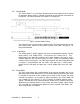
4.1.1 Master Mode The master mode is a stand-alone operating mode that requires only DC power for operation. Master mode is selected on the bank of DIP switches on the back of the camera. For mode selection see section 6.4.1 on page 18 . Figure 3 Master Mode Timing The exposure time in master mode is determined by the line period that is fixed at N+41 clock cycles, where N is the number of pixels. See Table 1 on page 8 for line period definition 4.1.1.
4.1.2.1 Exposure Control Slave mode camera exposure is determined by the LR and LT signals which must be timed with MCLK. The exposure time is defined as the time between the rising edge of the LR signal and the rising edge of the LT signal. The LR signal must be held active low (ON) for a minimum of 4 clock cycles and must be inactive high (OFF) for a minimum of 4 clock cycles prior to the LT signal rising edge.
4.1.3 Alt Slave Mode 1 Alt Slave Mode 1 operates similarly to the Slave Mode except that the camera operates on the internal camera clock CCLK (The basic camera model clock rate) while the exposure is determined by the externally applied LR and LT signals. There must be at least N+41 CCLK cycles between successive LT commands. 4.1.4 Alt Slave Mode 2 In Alt Slave Mode 2 the camera accepts a user supplied master clock MCLK and line transfer signal LT. The LR signal in this mode is ignored. 4.1.4.
5 Installation Guidelines The following guidelines are offered as an aid to permit the user for setting up the camera such that it can be verified for proper operation. Specific requirements are included only for items closely related to the camera operation. 5.1 Optical Interfacing The LC3000 series cameras require properly chosen lenses and lens extenders to allow the imaging of the chosen web width onto the sensor array.
5.1.1 Estimating the Working Distance The following relationships assume a thin lens relationship that is deemed sufficiently accurate to permit reasonably accurate estimates of the optical configuration.
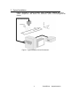
5.2 Lens Attachment The LC3000 series cameras provide threaded mounting holes on the front face of the cameras to allow the attachment of custom lens adapters. The lens mount is a M42 x 1 (Pentax) thread. PerkinElmer can provide such optical components as lenses, C and F style lens adapters, extension tubes, and focusing systems. Figure 6 shows the location of mounting holes and registration holes for the attachment of custom lens adapters. Figure 6 Camera Front Face Attachment Point Definition 5.
Figure 7 LC3000 Series Camera Mounting Hole Location Note: 5.4 For best thermal stability, mount the camera to a flat metal surface using the faceplate holes. Connecting Power Warning: It is the buyers responsibility to comply with all applicable code requirements. 5.4.1 Power Supply Requirements The power supply must provide at the camera: +11.4 to +25.
5.5 Interface Cabling The signal interface cable supports an RS-422 interface to receive the external LT, LR and MCLK signals and to output the LEN, CLT and CCLK signals. Additionally the cable connects power to the camera and provides the analog video output. Contact PerkinElmer for cabling options.
5.6 Frame Grabber Interface Guidelines The LC3000 series cameras have been designed for use with several brands of frame grabber. It is the users responsibility to select a frame grabber that is specific to the application being served and to provide any signal conditioning required to accept the differential analog video and support the RS-422 interface signals. When choosing a frame grabber, the following points must be observed: 1. Camera model (for number of pixels in sensor array). 2.
6 Camera Setup This section provides a generalized procedure for installing, configuring and activating your camera. Since every application is different, only suggested steps for a logical sequence to get the camera running are listed. It is assumed that you have familiarized yourself with the camera exposure and data output modes as described in4.1on section page5. 6.
7. Power up the system computer and verify that the frame grabber is operational. 6.2.1 Tripod Mounting The LC3000 series cameras are equipped with a ¼-20 UNC tripod mounting block that can be placed on any one of the 4 sides of the camera housing. Be sure to use 3 screws when employing the tripod mount.
6.3 Activating the Camera Place the test target within the cameras’ projected field of view and turn on the illumination source. Figure 8 Test Target Orient the test target such that the black and white Focusing Bars are directly below the camera and are aligned with the sensor array X direction as shown in Figure 9.
6.4 Camera Control Camera control includes camera operating mode, video offset and video gain. Each of these parameters is controlled by DIP switches accessible on the back of the camera. Figure 10 Camera Control DIP switch Location Note: Switch in the UP position is ON. 6.4.1 Camera Operating Mode Selection The camera operating mode is selected by DIP switches 1 and 2 as shown in Table 4.
6.4.3 Video Offset Video Offset is determined by DIP switches 6, 7 and 8 as shown in Table 6 Table 6 Video Offset Selection Range DIP Switch #6 0 ON 1 ON 2 ON 3 ON 4 OFF 5 OFF 6 OFF 7 OFF DIP Switch #7 ON ON OFF OFF ON ON OFF OFF DIP Switch #8 ON OFF ON OFF ON OFF ON OFF Nominal Offset (mV) 0 6.4 12.8 19.3 25.7 32.1 38.6 45.0 6.4.4 Camera Powerup 1. Set DIP Switch #1 and DIP Switch # 2 to ON (Switch Up) to select Master Mode. 2. Turn on the camera power. 6.4.5 Focusing the Camera 1.
6.5 Verifying Slave Mode Operation Note: In order to verify the Slave Mode you must have made provisions for the required external signals in the frame grabber interface as described in section on 4.1.2 page6. 1. Make sure that the camera is powered down. 2. Set DIP Switch #1 and DIP Switch #2 to OFF, OFF to select the Slave Mode. 3. Power up the camera. 4. Set the Line rate of the LT (Line Transfer) signal to: Line rate £ MCLK frequency N + 41 5. Set LR active in accordance with slave mode timing. 6.
7 Target Speed Determination 7.1 Target Speed and Exposure Relationships The following definitions apply: Image Resolution The number of pixels in the camera sensor array. Spatial Resolution The sensor array pixel dimensions mapped onto the web dimension X. (See Figure 5 on page 9) Feature Resolution The smallest feature to be imaged by the camera. The target speed derives from the chosen feature size D and is limited by the minimum Line Period values defined in Table 1 on page 8.
7.2 Sample Imaging Setup The following example assumes that you have determined the following: · Target width X · Image resolution # of pixels (By choice of camera) · Required feature resolution. i.e. the smallest feature dimension “D” to be detected. Example: To image a feature .020” dia. on an 18” web using a LC 3013 Camera. Satisfying the Nyquist criterion, the effective y sample size=0.01”. y eff Since the maximum line rate corresponding to the minimum line period from Table 1 on page 8 is 208 .
8 Troubleshooting 8.1 Troubleshooting Check List No Video 1. Verify that the power to the camera is on. 2. Verify that the frame grabber is operating properly. 3. Verify that the interface cable is securely attached to the camera. 4. Verify the interface cable continuity on each pin. 5. Make sure that the required control signals for the camera mode selected are present. Intermittent Video 1. Verify that all interface cable connections are securely attached. Blurry Video 1.
8.3 Contacting Customer Support United States PerkinElmer Optoelectronics 2175 Mission College Blvd. Santa Clara, CA 95054 Toll Free 800-775-OPTO (6786) Phone: +1-408-565-0830 Fax: +1-408-565-0703 Germany PerkinElmer Optoelectronics GmbH Wenzel- Jaksch-Str. 31 D-65199 Wiesbaden Germany Phone: +49-611-492-570 Fax: +49-611-492-165 Japan PerkinElmer Optoelectronics NEopt.
APPENDIX A Interface Guidelines A.1 RS-422 Digital Interface The LC3000 series digital signals are received and transmitted using balanced , differential circuits that comply with the data transmission standards set forth in the EIA RS-422 specification. All of the differential digital I/O signals on the D-sub 25 connector are labeled (+) or (-) to indicate polarity. The following definitions apply to each pair of associated signal lines: ON: When signal line (+) is more positive than (-).
A.
Index A O Alt Slave Mode 1, 8 Alt Slave Mode 2, 8 Operating Mode selection, 18 Optical Interfacing, 9 C P Camera activating, 17 installing, 15 mounting, 11 Operation overview, 5 Camera Control switches, 18 Camera Gain Control, 19 Camera Setup, 15 Customer Supplied Components, 4 Customer Support contacting, 24 Power Supply Requirements, 12 Product Overview, 1 R RMA, 23 RS-422 Digital interface, 25 S Sample Imaging Setup, 22 Slave Mode, 6 Slave Mode Operation verifying, 20 Slave Mode Timing, 7 D Dat