
Operating instructions

T
he Remote Control uses a CR2032 type Lithium cell
w
hich under normal conditions will have a typical life
i
n excess of 1 year. Under normal battery conditions
t
he LED on the Remote control will illuminate only
w
hen a button is pressed. However, under low-
b
attery conditions this LED will flash every time the
b
utton is pressed. When this occurs the battery
s
hould be replaced as soon as possible.
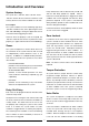
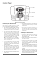
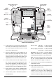
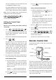
Setting the Remote Control
1.
Remove the front cover by undoing the small
screw on the rear of the Remote Control.
2.
Located above the battery is a row of 8 DIP
switches. Select and record a random combination
of ‘ON’ and ‘OFF’ positions for the DIP switches.
This will be the system House Code that enables
all elements of your transmitters to communicate
with the Control Panel.
Important: The House Code for your system should
be changed from the factory default setting.
3.
Ensure that the jumper link located immediately
below the House Code DIP switches is fitted in
position for use with this alarm system.
4.
Insert the battery under the clip ensuring that the
+v terminal faces upwards away from the PCB.
5.
Replace the front cover and fixing screw.
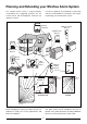
Passive Infrared (PIR)
Movement Detectors
PIR Detectors are designed to detect movement in
a protected area by detecting changes in infra-red
radiation levels caused, for example, when a person
moves within or across the devices field of vision.
I
f movement is detected an alarm signal will be
g
enerated, (if the system and alarm zone is armed).
N
ote: PIR Detectors will also detect animals, so
e
nsure that pets are not permitted access to areas
f
itted with Passive Infra Red Detectors when the
s
ystem is armed.
A
ny number of PIR Detectors can be used with your
s
ystem, providing they are all coded with the system
H
ouse Code and are mounted within effective radio
r
ange of the Control Panel.
The PIR Detector is powered by a PP3 Alkaline
battery which under normal conditions will have an
expected life in excess of 1 year. When the battery
level drops, with the PIR Detector in normal operation
mode and the battery cover fitted, the LED behind
the detection window will flash. When this occurs
the battery should be replaced as soon as possible.
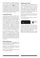
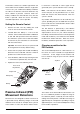
Choosing a position for the
PIR Detector
The recommended position for a PIR Detector is in
the corner of a room mounted at a height between
2 and 2.5m. At this height, the PIR Detector will
have a maximum range of up to 12m with a field of
view of 110°.
The Position of the PCB inside the PIR Detector can
be set to 5 different positions to adjust the range of
the detection pattern created by the PIR Detector.
Setting the PCB in position 3 will reduce the range to
approximately 9m, with position 1 providing a range of
approximately 6m. The recommended position setting
for the PCB is in position 5.
10
Battery Clip
House Code
Dip Switches
Jumper Link
Battery
Less Sensitive
More Sensitive
110°
12
10
8
6
4
2
0
2
4
6
8
10
12
0
2
4
6
metres
8
10
12
0
2
metres
Side View
Top View