
Specifications
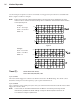


22 Performance Verification
Chapter 9 Performance Verification
Warning: Performance verification should be performed prior to each patient use of the
BiPAP System.
Note: For performance verification, Respironics recommends use of a manometer capable of
reading pressures in centimeters of water.
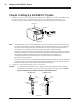
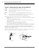
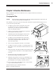
1. Connect the patient circuit following the Set-up Instructions in this manual. Connect the
proximal pressure tubing to one of the pressure ports on the mask or exhalation valve.
2. Connect the remaining end of the proximal pressure tubing to the manometer.
3. Adjust the settings on the control panel as follows:
Function Selector Knob: IPAP
Controls: IPAP 4 cm H
2
O
EPAP 4 cm H
2
O
BPM 10
%IPAP 30
4. Turn the BiPAP unit ON (I) and allow it to warm up for at least 15 minutes prior to
performance verification.
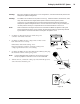
5. a. Occlude the circuit outlet.
b. Verify that the Function Selector Knob is set at the IPAP position.
c. Verify that the appropriate LED is illuminated.
d. Verify that the IPAP reading is 4 cm ± 2 cm H
2
O.
e. Adjust the IPAP setting to 10, 15, and then 20 cm H
2
O and verify corresponding readings.
f. Set the IPAP control to the maximum setting position.
g. Set the Function Selector Knob to the EPAP position and repeat Steps c, d, and e.
h. Set the EPAP control to 5 cm H
2
O and the IPAP control to 10 cm H
2
O.
6. a. Set the Function Selector Knob to the S mode.
b. Verify that the appropriate mode LED is illuminated.
c. Create a small leak to simulate a spontaneous trigger.
d. Observe that the unit cycles to IPAP and that the IPAP control illuminates. Verify that the
unit cycles to IPAP and remains there for approximately three seconds before cycling back to
EPAP. Once the unit cycles to EPAP, it should remain there for approximately 0.5 seconds
before cycling to IPAP. The unit will cycle between IPAP and EPAP up to five times.
e. Totally occlude the circuit.
7. a. Set the Function Selector Knob to the S/T mode.
b. Verify that the appropriate LED is illuminated.
c. Observe that the unit cycles between IPAP and EPAP. Observe that when the unit cycles
from EPAP to IPAP, the BPM LED illuminates. (The BPM LED may or may not remain
illuminated for the total cycle.)
d. When the DCP is in the EPAP mode (the EPAP LED is illuminated) with the BPM LED
illuminated, allow a small mask leak to simulate a spontaneous trigger. Observe that the
BPM LED does not illuminate.
e. Re-establish the mask seal.